
Owner`s manual

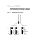


If self-test passes, the large yellow LED at the top of the LEDs is ON.
(Here self-test means the on-board power-up tests, RBD 0, the CPU/memory
interaction tests, RBD 1, and the multiprocessing tests, RBD 5.) The top
two red LEDs (next to the yellow one) are also ON, and the next five red
LEDs are OFF. The LED next to the Error LED is OFF if the processor is
the boot processor, and ON if it is a secondary processor.
If self-test fails, the yellow LED is OFF, and the top eight red LEDs contain
an error code that corresponds to the number of the failing test. The test
number is represented in binary-coded decimal, with the most significant
bit at the top. A bit is ONE if the light is ON.
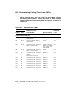
For example, assume a processor fails self-test (yellow LED is OFF) and
shows the following pattern in the top eight red LEDs:
TOP
(MSB) off 0
off 0 = 3
on 1
on 1
off 0
off 0
on 1 = 2
(LSB) off 0
BOTTOM
The failing test number decodes to 0011 0010 (binary-coded decimal 32). If
you then ran RBD 0 with the /TR and /HE qualifiers, the last test number
you would see displayed is T0032.
If either of the toptwo red LEDsis off, a failure hasoccurred during the self-
test sequence. But system power-up self-test actually comprises four sets of
tests: KA65A power-up tests (RBD 0), CPU/memory interaction tests (RBD
1), DWMBA or DWMBB tests (RBD 2), and multiprocessing tests (RBD 5).
Interpretation of the red LEDs depends on which set of tests was running,
as explained in Section B.2. Interpretation of the error LED is explained
in Section B.3.
Description of KA65A LEDs B–3