
Owner`s manual
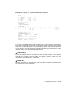


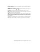


Table A–1 shows the maximum number of scalar and vector processors
supported in a VAX 6000 Model 500 system.
Table A–1: Processor Module Combinations
Maximum
Scalar
Processors
Maximum
Vector
Processors
Configuration
(Slot 1 at Right)
60PPPPPP
4 1 MVPPPP
2 2 MVPMVP
Figure A–2 shows system configurations for a VAX 6000 Model 500 system
with one or two vector processors. The left side of the figure indicates the
configuration for two scalar/vector pairs with a memory module in the slot
to the left of the vector processor. The right side of the figure shows a single
scalar/vector pair with additional scalar processors.
As described in Section A.1, processor modules are configured after I/O
adapters. (I/O adapters are installed, from left to right, in slots E to A and
then 5 to 1.) Processors are configured from right to left, filling available
slots starting with slot 1. Memories are configured last, from left to right,
filling available slots from 9 to 2. However, in a system with a vector
processor, the modules should be installed as shown in Figure A–2. These
configurations must be followed to avoid damage to the modules and for
performance reasons:
• Because the FV64A module has VLSI components with heat sinks
protruding from both sides, only a memory module, with its low
components, can be placed next to side 2 of the FV64A module.
• In a system with one scalar/vector pair and one or more additional
scalar processors, the scalar processor of the pair should be prevented
from being the boot processor for performance reasons.
If the scalar/vector pair is to the left of other scalar processors, then the
processor of the scalar/vector pair will not become the boot processor
unless other processors fail self-test or have been disabled with the
SET CPU console command. Alternatively, you can issue the SET
CPU/NOPRIMARY command and give the node number of the attached
scalar processor that you do not want to be the boot processor.
VAX 6000 Model 500 General Configuration Rules A–5