
User`s manual


7. Arrow Position Select - This icon prompts you to
press the TAB key (or “click” the icon directly with the
mouse cursor) to position the limit selector arrow at
either the upper or the lower end of the vertical marker.
You can toggle between the upper and lower positions
by pressing the TAB key repeatedly.
8. Up Arrow-This icon prompts you to press the up
arrow key to move the designated moveable end of the
vertical marker upward. (You can use the PgUp and
PgDn keys to move the end in larger increments.)
9. Down Arrow - This icon prompts you to press the
down arrow key to move the designated moveable end
of the vertical marker downward. (You can use the
PgUp and PgDn keys to move the end in larger
increments.)
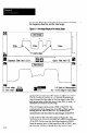
10. Cycle Time -The cycle time value displayed here is
the actual time that the SLS required to process the
current image. The time varies with the selected
analysis function and the exposure time. (For more
information about cycle tune, refer to Appendix B of
the SLS User’s Manual, Catalog No. 2804-NDOOl.)
11. Exposure Time - The exposure time value displayed
here is the actual time that the SLS required to capture
the current image. The time varies with the amount of
light in the FOV. (For more information about exposure
tune, refer to Appendix B of the SLS User’s Manual,
Catalog No. 280~NDOOl.)
12. *Edge Span and Edge Height - The values listed next
to “1)” and “2)” are the current Edge Span and Edge
Height parameters, respectively. Their purpose is to
enable you to mom precisely define the edges in order
to make them as stable as possible. In most cases, the
edges are sufficiently well defined for the default
values (4 for Edge Span and 3 for Edge Height) to
ensure stable edges. In a few cases, however, you may
need to adjust these parameters to accommodate less
well-defined edges, or to filter out unwanted “noise.”
(Refer to Edge Height and Edge Span Parameters on
page 6-11 for information about selecting and adjusting
these parameters.)
Note: This location is used to indicate the binary
threshold and light probe location values when the SLS
is configured with either the Binary Object Size or the
-
-
c-4
‘Not available in Main Menu View Image option.