
User`s manual


View Image Option
The SLS Configuration Support Software (CSS) provides
two versions of the View Image Option:
One version is in
the Main Menu, while the other version is in the
Configuration Menu. Since the Configuration Menu version
has the most functions, the information and procedures in
this chapter cover its functions, and they include notes to
indicate which functions do not apply the Main Menu
version.
The main purpose of the View Image display is to enable
you to see the image of the inspected object that the SLS
“sees” within its field of view (FOV). Using this display,
you can stage, aim, and focus the SLS more quickly and
accumtely. In addition, the View Image display enables you
to use a number of functions that cannot be used with a
stand-alone SLS.
Note: Before you continue with this chapter, perform the
procedure in Chapter 3, Getting Started, up to the point
where you have the View Image display shown in
Figure 3.12 (page 3-l 1) and in Figure 6.1 on page 6-2.
When you have that image on your PC’s display screen,
return to this chapter.
View Image Display:
Features and
Symbols
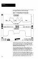
The View Image display (Figure 6.1) consists of two main
features: the Line Image, and the View Port. Briefly stated,
the Line Image is a graphic display of the light-and-dark
output from the linear sensor in the SLS. Below the Line
Image is the View Port, which is a user-adjustable,
“magnified” portion of the Line Image.
The following sections detail the features and symbols
within the View Image display.
Line Image
As stated above, the Line Image comes from the linear
sensor in the SLS. The inspection direction along the linear
sensor is from the bottom (mounting side) to the top of the
SLS, as shown in Figure 6.2 on page 6-3. In the Lie
Image, this corresponds to left-to-right. Thus, the SLS
--” the solid black bar first and the black-grayblack