
User`s manual


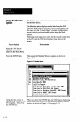


Figure 3.11 View Image Display of the Aiming Target
piixiq
I
t
Black bar Black-gray-black
white
/
c
\
White
1) First edge: 28.5~
2) Last edge: 75.3x
1-D Spatial ?kcasuraent
KS = first edge il last edge
The View Image contains two graphic displays: the Line
Image, and the View Port.
The Line Image represents the full image field of the SLS.
Since the SLS acquires an image from the bottom up
(Figure 3.1, page 3-Z), it “sees” the solid black bar first,
then the black-gray-black bar. Note that the black portions
of the Line Image are highest, the white portions lowest,
and the gray portion in between.
The View Port is, in effect, a magnified part of the Line
Image. The magnification is adjustable both vertically and
horizontally.
Note that if the “Locate Edges” example configuration
record had specified Light Object instead of Dark Object
(see switch settings in Figure 3.7, page 3-7), the images
would be inverted, as shown in Figure 3.12 on page 3-11.
3-10