
User`s manual


-
Use the space bar and
Note that the Remote Configuration switch is not included
ENTER key to conjigure the
remaining switches as
in this group. That switch can be set only on the SLS itself.
shown in Figure 3.7.
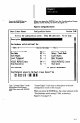
Figure 3.7 shows how the parameter switches are set for the
“Locate Edges” example configuration record. “Off’
selects the parameter in the left column, while “On” selects
the parameter in the right column.
Figure 3.7 ParameterSwitchConfiguration
II
-(Off I Mitch Settings-
Ion) 1
Targeting Light Off
Off <--
Run tlode on -->
Dark Object
Off <--
Level Iriggered
Off (--
Normal Lighting
Off <--
Output Norrrally Open
Off <--
High Resolution
m
Targeting Light On
Setup 1 Teach tlode
Light Object
Edge Ir iggered
Strobe Lighting
Output Normally Closed
High Speed
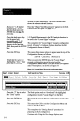
When you press the ENTER key after setting the last
switch, the cursor advances to the “SLS Function” field and
the SLS Function Selection Menu appears on the screen, as
shown in Figure 3.8.
Figure38 SLSAnalysisFunctionSeietion
.-
tings- ml) 1
1-D Spatial lleasurenent
Object Width Neasurenent
Targeting Light On
Object Void Heasurenent >
Setup / Teach Mode
Largest Object Width
Light Object
1-D Object JIecognit ion
Edge Triggered
Included Obj. lexture Recognition
Strobe Lighting
Full Field Texture Recognition
Output Normally Closed
High Speed
SLS Function
The function selection menu contains all of the SLS
analysis functions (they do not all appear at the same time
3-7