User`s manual
Manuals
Brands
Vax Manuals
Household Appliances
V-002
191
192
193
194
195
196
197
198
199
200
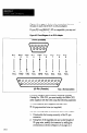
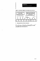
Figure
A.3
Schematic
Diagram
for
Modifying
2!i-pin
Connector
3.
Reassemble
the
25-pin
connector.
Note:
Using
a
modified
cable
with
other
IBM-compatible
PC’s
may
result
in
unsatisfactory
performance.
Use
the
unmodified
cable
with
those
PCs.
.-
--
A-3
1
...
...
193
194
195
196
197
...
...
228