
User`s manual


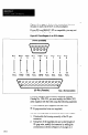
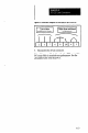


Figure A.2 on page A-2 shows the connections between
the pins on each end of the o-to-25 pin adapter.
If your PC is an IBM-PC, XT or compatible, you may not
need the o-to-25 pin adapter.
Fgure A.2 Pinout Diagram: 9-b-25 Pin Adapter
O-Pin (Female)
(pG-&)
N.C.
RXD TXD N.C. GRD N.C. N.C. NC. N.C.
1 2 3 4
5 6 7 8 9
II I
8 3 2
N.C. RXD TXD Ifit. GkD N’C. N:C. N%. i:.
25-Pin (Female)
N.C. = No Connection
-
-
If you are using an Allen-Bradley industrial terminal,
Catalog No. 1784T45, you must modify the 280~CSCl
cable supplied with the CSS, using the following materials:
l Five connector pins (supplied with the CSS).
l 22-gage insulated wire (not supplied).
-
Use the following steps to modify the 2804-CSCl cable:
1. Disassemble the housing assembly of the 25-pin
connector.
2. Using five of the supplied pins and a short length of
22-gage wire, modify the connector by adding the
connections as shown in Figure A.3 on page A-3.
A-2