
User`s manual


-
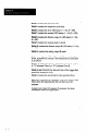
Field 4 contains the exposure time.
Field 5 contains the inspection cycle time.
Field 6 contains the error LED status (1 = On; 0 = Off).
Field 7 contains the contrast LED status (1 = On; 0 = Off).
Field 8 contains the discrete output A LED status (1 = On;
O-Off).
Field 9 contains the analog output A result.
Field 10 contains the discrete output B LED status (1 = On;
o-off).
Field 11 contains the analog output B result.
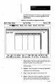
In the second group of three lines, each line contains four
fields, separated by commas. The information in each field
is as follows:
Field 1 identifies the chart to which the results data applies.
-
A “5” indicates Chart A; a “6” indicates Chart B.
Fields 2 and 3 identify the date and time of the trigger that
started the inspection cycle.
Field 4 contains the results data for the specified chart.
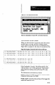
When the conversion is completed, a message appears with
instructions for importing the file into the Lotus 123
Program.
Consult your Lotus 123 manual, if necessary, for more
information about fiie importation.
8-56