
User`s manual


-
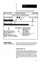
l Max-This is the current maximum result value.
l
Min - This is the current minimum result value.
l Range - This is the difirence between the current
maximum and minimum result values.
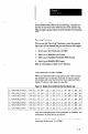
Switch Settings @
These “switch settings” are the operating parameters in the
current SLS configuration. They reflect the parameters
designated by either the DIP switch settings on the SLS or
the “switch settings” contained in a downloaded
configuration.
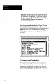
Miscellaneous Data @
These six lines include information about the current SLS
configuration and performance data about each inspection
operation, as follows:
l Configuration - This indicates whether the SLS is
currently operating using a “remote configuration,” or is
using the “hardware switches.” The difference is this:
When using a “remote configuration,” the SLS uses the
operating parameters and analysis function defined in a
configuration record. When using the “hardware
switches,” the SLS uses the operating parameters and
analysis function defined by the settings of the DIP
switches on the SLS.
l Lighting Compensation - This indicates whether the
lighting compensation is currently enabled (On) or
disabled (Off). (Refer to Chapter 6, View Image Option,
for detailsabout the lighting compensation function.)
l Exposure Time - This indicates the amount of time that
the SLS required to expose the linear sensor adequately
for the current image. The exposure time varies with
changes in FOV luminance levels.
l Cycle Time - This indicates the total time that the SLS
required to expose, acquire, and process the current
image. The cycle time is the minimum acceptable time
interval between triggers.
l Triggers Processed - This line indicates the number of
triggers that the SLS processed vs the number of triggers
that it received.
7-5