
Specifications


Introduction
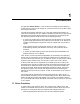
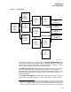
1.3 I/O Database
Figure 1–1 I/O Database
ZK−1766−GE
FDT Routine
Driver
Start I/O Routine
Driver
Routine
Interrupt Service
Driver
registers
Device
controller)
(synchronizes
CRB
device)
(describes
UCB
to device)
logical path
(describes
CCB
request)
I/O
(describes
Packet
Request
I/O
controller)
(describes
IDB
DDB
adapter)
(describes
ADP
process
requesting
describes
Block
Control
Process
Routine
Controller Initialization
Driver
(locates
DDT
(
)
for device
(
type)
driver)
The system also creates for each controller an interrupt dispatch block (IDB).
An IDB lists the device units associated with a controller and points to the UCB
of the device unit that the controller is currently servicing. In addition, an IDB
points to device registers and the controller’s I/O adapter.
An adapter control block (ADP) defines the characteristics and current state
of an I/O adapter such as the TURBOchannel interface on a DEC 3000. An
ADP contains the information necessary to allocate the adapter’s resources. The
operating system provides routines that drivers can call to interface with the
appropriate adapter.
The channel control block (CCB) describes the logical path between a process
and the UCB of a specific device unit.
2
Each process owns a number of CCBs.
2
Channel request blocks (CRBs) and channel control blocks (CCBs) are two separate data
structures. To help distinguish the two, it may be helpful to think of the channel request
block as the ‘‘controller request’’ block because it describes the hardware controller. In
contrast, the channel control block is used by a process and a device unit to manage the
1–5