
Specifications


Introduction
1.3 I/O Database
1.3 I/O Database
Because a driver and the operating system cooperate to process an I/O request,
they must have a common and current source of information about the request.
This is the function of the I/O database. The I/O database consists of the
following three parts:
• Driver tables that allow the system to load drivers, to validate device
functions, and to call driver routines at their entry points
• Data structures that describe I/O bus adapters, device types, device units,
device controllers, and logical paths from processes to devices
• I/O request packets that define individual requests for I/O activity
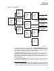
Illustrations of I/O database structures and detailed descriptions of their fields
appear in the data structure chapter of the OpenVMS AXP Device Support:
Reference. Figure 1–1 illustrates some of the relationships among system I/O
routines, the I/O database, and a device driver.
1.3.1 Driver Tables
The three driver tables—driver prologue table, driver dispatch table, and function
decision table—are defined in every driver. Section 1.2 lists these tables and the
other components of a device driver, and Chapter 4 discusses their contents.
1.3.2 Data Structures
I/O database data structures describe peripheral hardware and are used by the
operating system to synchronize access to devices. The operating system creates
these data structures either at system startup or when a driver is loaded into the
system.
The system defines a unit control block (UCB) for each device unit attached to
the system. A UCB defines the characteristics and current state of an individual
device unit.
UCBs are the focal point of the I/O database. When a driver is suspended or
interrupted, the UCB keeps the context of the driver in a set of fields collectively
known as a fork block.
1
In addition, the UCB contains the listhead for the
queue of pending I/O request packets (IRPs) for the unit.
A device data block (DDB) contains information common to all devices of the
same type that are connected to a particular controller. It records the generic
device name concatenated with the controller designator (for example, LPA,
DKB), and the name and location of the associated device driver. In addition,
the DDB contains a pointer to the first UCB for the device units attached to the
controller.
The operating system creates a channel request block (CRB) for each
controller. A CRB defines the current state of the controller and lists the
devices waiting for the controller’s data channel. It also contains a pointer to the
interrupt service routine (ISR).
1
Other structures, such as the CRB, also include a fork block. The discussion of fork
blocks and fork processes in Section 1.5 explains the role of fork blocks in driver
processing.
1–4