
Specifications


B Sample Driver Written in C
B.1 LRDRIVER Example . ........................................ B–1
B.2 LRDRIVER.COM ............................................ B–23
Index
Examples
9–1 Linker Options File (xxDRIVER_LNK.OPT) for an OpenVMS AXP
Device Driver ............................................ 9–3
11–1 Invoking the System-Code Debugger . . . ....................... 11–15
11–2 Connecting to the Target System ............................. 11–16
11–3 Target System Connection Display............................ 11–16
11–4 Setting a Breakpoint ...................................... 11–16
11–5 Finding the Source Code . . . ................................ 11–18
11–6 Using the Set Mode Screen Command . . ....................... 11–18
11–7 Using the SCROLL/UP DEBUG Command ..................... 11–19
11–8 Break Point Display ....................................... 11–20
11–9 Using the Debug Step Command ............................. 11–21
11–10 Using the Examine and Show Calls Commands . . ............... 11–22
11–11 Canceling the Breakpoints . . ................................ 11–23
11–12 Using the Step Command . . ................................ 11–24
11–13 Using the Step/Return Command ............................ 11–25
11–14 Source Lines Error Message ................................ 11–26
11–15 Using the Show Image Command ............................ 11–27
Figures
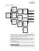
1–1 I/O Database ............................................ 1–5
4–1 Layout of Function Decision Table (FDT) ....................... 4–4
5–1 Format of System Buffer for a Buffered-I/O Read Function . . ....... 5–9
10–1 Traditional and Sliced Loads ................................ 10–13
10–2 XDELTA Display . ........................................ 10–15
12–1 Option Register Layout .................................... 12–3
12–2 Option Register Layout—Dense Space . . ....................... 12–3
12–3 Option Register Layout—Sparse Space . ....................... 12–3
12–4 Option Register Layout—Dense Space . . ....................... 12–4
12–5 Option Register Layout—Sparse Space . ....................... 12–5
12–6 Option Register Layout .................................... 12–7
12–7 Option Register Layout—Sparse Space . ....................... 12–7
12–8 Scatter/Gather Map Entry . . ................................ 12–9
12–9 TURBOchannel DMA Address ............................... 12–10
12–10 IOSLOT Register . ........................................ 12–12
12–11 IMASK . ................................................ 12–12
12–12 DEC 3000 Model 500 ADP List .............................. 12–14
12–13 DEC 3000 Model 400 ADP List .............................. 12–17
12–14 DEC 3000 Model 300 ADP List .............................. 12–19
xi