. • Table initialization code will be collected in a PSECT using a TBD pragma, so that the space it occupies can be deallocated after initialization.Writing Device-Driver Tables 4.4 Building Driver Tables Using C Table 4–2 (Cont.) DPT Initialization Macros for C Macro name Data type of second parameter Prototype value ini_dpt_vector pointer to vector of pointers 0 The following example shows the usage of the DPT initialization macros. extern DPT driver$dpt; /* Declare protype DPT */ ini_dpt_name ini_dpt_ucbsize ini_dpt_adapt ini_dpt_end (&driver$dpt, "XXDRIVER"); (&driver$dpt, sizeof(XX_UCB)); (&driver$dpt, AT$_NULL); (&driver$dpt); 4.4.1.
Writing Device-Driver Tables 4.
Writing Device-Driver Tables 4.
Writing Device-Driver Tables 4.4 Building Driver Tables Using C 4.4.3.1 FDT Functions The driver$ini_fdt_act function initializes the action routine and buffered function mask fields in the FDT. The driver$ini_fdt_end function signals that initialization of the FDT is complete. The bufflag parameter has the value BUFFERED if the function is buffered, NOT_BUFFERED or DIRECT otherwise.
5 Writing FDT Routines A driver performs device-specific I/O function preprocessing to validate arguments specified in the original call to the $QIO system service, to complete certain types of function processing such as set mode and sense mode operations, and to prepare to service functions involving a device transaction. Driver I/O function preprocessing on OpenVMS AXP systems often requires the cooperative efforts of upper-level FDT action routines, FDT support routines, and FDT completion routines.
Writing FDT Routines Note that FDT support routines and FDT completion routines return status to their callers. Each FDT routine that participates in the processing of an I/O function should examine the status value returned to it by any routine it calls and should reflect this status to the routine that called it. 5.1 Context of Driver FDT Processing The $QIO system service executes in the context of the process that issues the I/O request, but in kernel mode and at IPL$_ASTDEL.
Writing FDT Routines 5.2 Upper-Level FDT Action Routines Before exiting, the upper-level FDT action routine takes steps to complete FDT processing. Typically, these steps include: • Calling an FDT completion routine, which takes steps to complete the processing of an I/O request or to deliver the I/O request to the driver. An FDT completion routine typically provides the final $QIO completion status in the FDT_CONTEXT structure and returns SS$_FDT_COMPL warning status to its caller.
Writing FDT Routines 5.2 Upper-Level FDT Action Routines Table 5–1 (Cont.
Writing FDT Routines 5.2 Upper-Level FDT Action Routines • Whether an error is found in the I/O request. • Whether the operation is complete. • Whether the I/O operation requires and is ready for device activity. Any specific I/O function can be processed by only one upper-level FDT action routine.
Writing FDT Routines 5.2 Upper-Level FDT Action Routines Table 5–2 (Cont.) FDT Completion Macros and Associated Routines Macro Operation Be aware that programming a device driver to process simultaneous I/O requests requires detailed knowledge of the internal design of the operating system. A driver that uses the CALL_ALTQUEPKT macro must not only maintain its internal queues but must also synchronize those queues with the unit’s pending-I/O queue, which the operating system maintains.
Writing FDT Routines 5.2 Upper-Level FDT Action Routines Table 5–2 (Cont.) FDT Completion Macros and Associated Routines Macro Operation CALL_ QIODRVPKT Calls EXE_STD$QIODRVPKT to transfer control to a system routine (EXE_STD$INSIOQ) that either delivers an IRP immediately to a driver’s start-I/O routine or places the IRP in a pending-I/O queue waiting for driver servicing.
Writing FDT Routines 5.4 FDT Routines for System Buffered I/O 5.4.1 Checking Accessibility of the User’s Buffer First the FDT routine invokes the CALL_READCHK or CALL_WRITECHK macros (which call EXE_STD$READCHK or EXE_STD$WRITECHK, respectively) to confirm write or read access to the user’s buffer. Both of these routines write the transfer byte count into IRP$L_BCNT. EXE_STD$READCHK also sets IRP$V_FUNC in IRP$L_STS to indicate that it is a read function. 5.4.
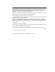
Writing FDT Routines 5.4 FDT Routines for System Buffered I/O Figure 5–1 Format of System Buffer for a Buffered-I/O Read Function System Space System Buffer Address of Data Area User Buffer Address Header Size Type Buffer Data Area Process Space User Buffer ZK−0927−GE 2. If IRP$L_SVAPTE is nonzero, assumes a system buffer was allocated and checks to see whether IRP$V_FUNC is set in IRP$L_STS. 3.
6 Writing a Start-I/O Routine A driver start-I/O routine activates a device and then waits for a device interrupt or timeout. This chapter describes the start-I/O routine. Chapter 8 describes the reactivation of the driver routine that performs device-dependent I/O postprocessing. With a few exceptions, the start-I/O routine discussed in the following sections describes a direct-memory-access (DMA) transfer using a single-unit controller. 6.
Writing a Start-I/O Routine 6.2 Context of a Driver Fork Process The start-I/O routine must preserve all general registers except R0, R1, R2, and R4. Before the packet-queuing routines call the start-I/O routine, they copy the following IRP fields into their corresponding slots in the device’s UCB: • • • ! UCB$_BCNT IRP$_BOFF ! UCB$_BOFF IRP$L_SVAPTE ! UCB$L_SVAPTE IRP$L_BCNT 6.3 Functions of a Start-I/O Routine The processing performed by a start-I/O routine is device specific.
Writing a Start-I/O Routine 6.3 Functions of a Start-I/O Routine If the channel is available, IOC_STD$PRIMITIVE_REQCHANL locates the interrupt dispatch block (IDB) for the channel with a pointer in the UCB: UCB ! CRB ! IDB The driver for a unit attached to a dedicated controller must contain the code needed to load the IDB address into R4. IOC_STD$PRIMITIVE_REQCHANL also writes the address of the new channelowner’s UCB in the owner field of the IDB (IDB$L_OWNER).
Writing a Start-I/O Routine 6.3 Functions of a Start-I/O Routine If the bit is set, a power failure might have occurred between the time that the start-I/O routine wrote the first device register and the time that the start-I/O routine is ready to activate the device. Such a power failure could modify the already-written device registers and cause unpredictable device behavior if the device were to be started. If the bit UCB$V_POWER is set, the start-I/O routine branches to an error handler in the driver.
7 Writing an Interrupt Service Routine When a device generates a hardware interrupt, it requests an interrupt at the appropriate device interrupt priority level (IPL). Either the device or its adapter requests a processor interrupt at that IPL. When the processor executes at an IPL below that device IPL, interrupt dispatching begins. The mechanism of interrupt dispatching has no direct bearing on the contents of a driver’s interrupt service routine.
Writing an Interrupt Service Routine 7.1 Servicing a Solicited Interrupt A driver’s interrupt service routine performs the following tasks to process the interrupt and transfer control to the waiting driver: 1. Obtains the address of the device’s UCB from the IDB, as follows: 4(AP) ! CRB ! IDB ! IDB$L_OWNER ! UCB The interrupt service routine restores the UCB address to R5. 2. Issues the DEVICELOCK macro to obtain synchronized access to device registers. 3.
Writing an Interrupt Service Routine 7.2 Servicing an Unsolicited Interrupt 7.2 Servicing an Unsolicited Interrupt A device requests an interrupt to indicate to a driver that the device has changed status. If a driver’s fork process starts an I/O operation on a device, the driver expects to receive an interrupt from the device when the I/O operation completes or an error occurs. Other changes in the device’s status occur when the device has not been activated by a device driver.
Writing an Interrupt Service Routine 7.2 Servicing an Unsolicited Interrupt The system routine that creates the fork process (once these conditions are satisfied) returns control to the interrupt service routine. The interrupt service routine then releases the device lock, restores the saved registers, and issues an REI instruction to dismiss the interrupt.
8 Completing an I/O Request and Handling Timeouts Once a driver has activated the device and invoked the wait-for-interrupt macro, the driver remains suspended until the device requests an interrupt or times out. If the device requests an interrupt, the driver’s interrupt service routine handles the interrupt and then reactivates the driver at the instruction following the wait-for-interrupt macro. The reactivated driver performs device-dependent I/O postprocessing.
Completing an I/O Request and Handling Timeouts 8.1 I/O Postprocessing The steps listed previously move the fork process context into the UCB’s fork block. They save R3 through R5 and the driver’s PC address. The driver’s fork process resumes processing when the system fork dispatcher dequeues the UCB fork block from the fork queue, and reactivates the driver at the driver’s fork IPL. 8.1.
Completing an I/O Request and Handling Timeouts 8.1 I/O Postprocessing 8.1.2.3 Returning Control to the Operating System Finally, the driver fork process returns control to the system by invoking the REQCOM macro to complete the I/O request. REQCOM calls the system routine IOC_STD$REQCOM. IOC_STD$REQCOM locates the address of the I/O request packet (IRP) corresponding to the I/O operation in the device’s UCB (UCB$L_ IRP).
Completing an I/O Request and Handling Timeouts 8.2 Timeout Handling Routines 1. It obtains both the fork lock and the device lock associated with the device unit to synchronize access to its fork database and device database. It raises IPL to device IPL as a result of obtaining the device lock. 2. It raises IPL on the local processor to IPL$_POWER to block local power failure servicing. 3.
Completing an I/O Request and Handling Timeouts 8.2 Timeout Handling Routines • It sends a message to an operator mailbox and waits for a subsequent interrupt or timeout. 8.2.1 Retrying an I/O Operation Some devices might retry an I/O operation after a timeout. For example, a disk driver’s timeout handling routine might take the following steps after a transfer timeout: 1. Invokes the FORK macro to lower IPL to fork level. 2. Releases any owned map registers, data path, and controller data channel. 3.
Completing an I/O Request and Handling Timeouts 8.2 Timeout Handling Routines 5. Clears bits 16 through 31 in R0 to indicate that no data was transferred 6. Issues the REQCOM macro to complete the request 8.2.3 Sending a Message to the Operator The following sequence describes a timeout handling routine that sends a message to the operator’s mailbox and then goes back into a wait-for-interrupt or timeout state on the presumption that subsequent human intervention will make the device operational: 1.
Completing an I/O Request and Handling Timeouts 8.2 Timeout Handling Routines g. Issues a SETIPL macro to raise IPL$_POWER and prevent power failure interrupts on the local processor. h. Invokes the WFIKPCH macro to wait for another interrupt or timeout. When the OPCOM process reads the message in its mailbox, it sends the requested message, in this case ‘‘device-offline,’’ to all operator terminals enabled for that device class.
9 Linking a Device Driver Use the following LINK command line as the model for the command line to link your OpenVMS AXP device driver. Brief descriptions of each qualifier used in this command follow. See the OpenVMS Linker Utility Manual for more detailed information.
Linking a Device Driver /SYSEXE Directs the linker to selectively search the system shareable image, SYS$BASE_ IMAGE.EXE, to resolve symbols in a link operation. When the linker selectively searches SYS$BASE_IMAGE.EXE, it only includes symbols from its global symbol table that were referenced by input files previously processed in the link operation. /DSF Directs the linker to create a file called a debug symbol file (DSF) for use by the OpenVMS AXP System-Code Debugger.
Linking a Device Driver 9.1 Linker Options File for OpenVMS AXP Device Drivers Example 9–1 Linker Options File (xxDRIVER_LNK.OPT) for an OpenVMS AXP Device Driver ! ! Define symbol table for SDA using all global symbols, not just ! universal ones ! SYMBOL_TABLE=GLOBALS ! ! This cluster is used to control the order of symbol resolution. All ! psects must be collected off of this cluster so that it generates ! no image sections. ! CLUSTER=VMSDRIVER,,,! ! Start with the driver module ! XXDRIVER.
Linking a Device Driver 9.1 Linker Options File for OpenVMS AXP Device Drivers Example 9–1 (Cont.) Linker Options File (xxDRIVER_LNK.
Linking a Device Driver 9.2 Resolving CRTL References at Link-Time However, execlets and user-written system services typically link /NOSYSSHR and resolve external symbols without references to other shareable images. Two options exist for resolving CRTL symbols at link time without references to DECC$SHR.EXE: • Resolving them out of STARLET.OLB (all the objects that comprise DECC$SHR.EXE exist in STARLET.OLB) • Link /SYSEXE and resolving the symbols from SYS$BASE_IMAGE.EXE (the kernel CRTL).
10 Loading an OpenVMS AXP Device Driver An OpenVMS AXP device driver, as discussed in Chapter 9, is created as an executive image. It is loaded as an integral part of the executive by the executive loader. You use the System Management utility (SYSMAN) to interface with the system loader. This chapter describes the procedures you should follow to load an OpenVMS AXP device driver for testing on an AXP system: • Section 10.1 describes a general method for configuring I/O devices and loading their drivers.
Loading an OpenVMS AXP Device Driver 10.1 Manually Connecting Devices and Loading Drivers 10.1.2 Obtaining the Adapter’s CSR Address When connecting a device, the driver loading procedure creates a UCB, CRB, and IDB for it and copies the value of the csr parameter of the IO CONNECT command directly to the IDB$Q_CSR field in the IDB. In general, when manually connecting a device, you should specify the base CSR address of the device register space.
Loading an OpenVMS AXP Device Driver 10.2 I/O Configuration Support in SYSMAN 10.2 I/O Configuration Support in SYSMAN On OpenVMS AXP systems, SYSMAN is used to connect devices, load I/O device drivers, and display configuration information useful for debugging device drivers. Enter the following command to invoke SYSMAN: $ MCR SYSMAN The SYSMAN prompt SYSMAN> appears. All SYSMAN commands that control and display the I/O configuration of an OpenVMS AXP system must be introduced with the prefix IO.
AUTOCONFIGURE AUTOCONFIGURE Automatically identifies and configures all hardware devices attached to a system. The AUTOCONFIGURE command connects devices and loads their drivers. You must have CMKRNL and SYSLCK privileges to use the AUTOCONFIGURE command. Format IO AUTOCONFIGURE Parameters None. Description The AUTOCONFIGURE command identifies and configures all hardware devices attached to a system. It connects devices and loads their drivers.
CONNECT CONNECT Connects a hardware device and loads its driver, if the driver is not already loaded. You must have CMKRNL and SYSLCK privileges to use the CONNECT command. Format IO CONNECT device-name[:] Parameters device-name[:] Specifies the name of the hardware device to be connected. It should be specified in the format device-type, controller, and unit number (for example, LPA0 where LP is a line printer on controller A at unit number 0).
CONNECT /LOG=(ALL,CRB,DDB,DPT,IDB,SB,UCB) /NOLOG (default) Controls whether SYSMAN displays the addresses of the specified control blocks. The default value for the /LOG qualifier is /LOG=ALL. If /LOG=UCB is specified, a message similar to the following is displayed: %SYSMAN-I-IOADDRESS, the UCB is located at address 805AB000 The default is /NOLOG. /MAX_UNITS=maximum-number-of-units Specifies the maximum number of units the driver can support.
CONNECT Examples 1. SYSMAN> IO CONNECT DKA0:/DRIVER_NAME=SYS$DKDRIVER/CSR=%X80AD00/ADAPTER=4/NUM_VEC=3/VECTOR_SPACING=%X10/VECTOR=%XA20/LOG %SYSMAN-I-IOADDRESS, the CRB is located at address 805AEC40 %SYSMAN-I-IOADDRESS, the DDB is located at address 805AA740 %SYSMAN-I-IOADDRESS, the DPT is located at address 80D2A000 %SYSMAN-I-IOADDRESS, the IDB is located at address 805AEE80 %SYSMAN-I-IOADDRESS, the SB is located at address 80417F80 %SYSMAN-I-IOADDRESS, the UCB is located at address 805B68C0 2.
SET PREFIX SET PREFIX Sets the prefix list which is used to manufacture the IOGEN Configuration Building Module (ICBM) names. Format IO SET PREFIX=(icbm_prefix[,...]) Parameters icbm_prefix[,...] Specifies ICBM prefixes. These prefixes are used by the AUTOCONFIGURE command to build ICBM image names. Description The SET PREFIX command sets the prefix list which is used to manufacture SYSMAN Configuration Building Module (ICBM) names. Qualifiers None.
SHOW BUS SHOW BUS Lists all the buses, node numbers, bus names, TR numbers and base CSR addresses. You must have CMKRNL privilege to use SHOW BUS. Format IO SHOW BUS Parameters None. Description The SHOW BUS command lists all the buses, node numbers, bus names, TR numbers and base CSR addresses. You must have CMKRNL privilege to use SHOW BUS. Qualifiers None.
SHOW DEVICE SHOW DEVICE Displays information on device drivers loaded into the system, the devices connected to them, and their I/O databases. All addresses are in hexadecimal and are virtual. Format IO SHOW DEVICE Parameters None. Qualifiers None. Description The SHOW DEVICE command displays information on the device drivers loaded into the system, the devices connected to them, and their I/O databases.
SHOW DEVICE __Driver________Dev_DDB______CRB______IDB______Unit_UCB_____ SYS$FTDRIVER FTA 802CE930 802D1250 802D04C0 0 801C3710 SYS$EUDRIVER EUA 802D0D80 802D1330 802D0D10 0 801E35A0 SYS$DKDRIVER DKI 802D0FB0 802D0F40 802D0E60 0 801E2520 SYS$PKADRIVER PKI 802D1100 802D13A0 802D1090 0 801E1210 SYS$TTDRIVER OPERATOR NLDRIVER 10–11
SHOW PREFIX SHOW PREFIX Displays the current prefix list used in the manufacture of ICBM names. Format IO SHOW PREFIX Parameters None. Description The SHOW PREFIX command displays the current prefix list on the console. This list is used by the AUTOCONFIGURE command to build ICBM names. Qualifiers None.
Loading an OpenVMS AXP Device Driver 10.3 Loading Sliced Executive Images 10.3 Loading Sliced Executive Images In traditional executive image loading, code and data are sparsely laid out in system address space. The loader allocates the virtual address space for executive images so that the image sections are loaded on the same boundaries as the linker created them. The images are normally linked with the /BPAGE qualifier equal to 14; this puts the image sections on 16 KB boundaries.
Loading an OpenVMS AXP Device Driver 10.3 Loading Sliced Executive Images 10.3.1 Controlling Executive Image Slicing The system parameter LOAD_SYS_IMAGES is a bitmask and has several bits defined: • SGN$V_LOAD_SYS_IMAGES (bit 0)—Enables loading alternate executive images specified in VMS$SYSTEM_IMAGES.
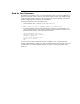
Loading an OpenVMS AXP Device Driver 10.3 Loading Sliced Executive Images Figure 10–2 XDELTA Display Full display: ;L Seq# Image Name Base End 0012 EXEC_INIT.EXE 0010 SYS$CPU_ROUTINES_0101.EXE Nonpaged read only Nonpaged read/write Initialization 000E ERRORLOG.EXE Nonpaged read only Nonpaged read/write Initialization 000C SYSTEM_SYNCHRONIZATION.EXE Nonpaged read only Nonpaged read/write Initialization . . . . . . . . . . . . . . . 0002 SYS$BASE_IMAGE.
Loading an OpenVMS AXP Device Driver 10.3 Loading Sliced Executive Images 4. Add the value calculated in step 2 (2530) to the base address for the image section (0). The sum (2530) is the offset within the image as written by the linker. 5. Look at the ‘‘Program Section Synopsis’’ section of the linker map. Using the offset (2530) determined in step 4, you find that the address is in module SMPROUT.
11 Debugging a Device Driver The OpenVMS Delta and XDelta Debuggers (DELTA/XDELTA) and the OpenVMS AXP System-Code Debugger (system-code debugger) are tools you can use to debug device drivers. This chapter briefly describes DELTA/XDELTA, and it explains how to use the system-code debugger. 11.1 Using the Delta/XDelta Debugger The OpenVMS Delta/XDelta Debugger (DELTA/XDELTA) is a primitive debugger.
Debugging a Device Driver 11.1 Using the Delta/XDelta Debugger For more information about using DELTA/XDELTA, see the OpenVMS Delta /XDelta Debugger Manual. 11.2 Using the OpenVMS AXP System-Code Debugger The OpenVMS AXP System-Code Debugger (system-code debugger) can be used to debug nonpageable system code and device drivers running at any interupt priority level (IPL).
Debugging a Device Driver 11.2 Using the OpenVMS AXP System-Code Debugger Note that you can also use OpenVMS Debugger commands with the DECwindows Motif interface. • A character cell interface for terminals and workstations When using this interface, you interact with the system-code debugger by entering commands at a prompt. The sections in this chapter describe how to use the system-code debugger with the character cell interface.
Debugging a Device Driver 11.2 Using the OpenVMS AXP System-Code Debugger Boot Command The form of the boot command varies depending on the type of OpenVMS AXP system you are using. However, all boot commands have the concept of boot flag and boot devices as well as a way to save the default boot flags and devices. This section uses syntax from a DEC 3000 Model 400 AXP Workstation in examples. To use the system-code debugger, you must specify an Ethernet device with the boot command on the target system.
Debugging a Device Driver 11.2 Using the OpenVMS AXP System-Code Debugger Boot Command Example The following command boots a DEC 3000 Model 400 from the dka0 disk, enables the system-code debugger, defaults to using XDELTA, and takes the initial system boot breakpoints: >>> boot dka0,esa0 -fl 0,8006 You can set these devices and flags to be the default values so that you will not have to specify them each time you boot the system.
Debugging a Device Driver 11.2 Using the OpenVMS AXP System-Code Debugger If the system-code debugger is already connected, the ;R command transfers control to the system-code debugger, and optionally changes the password that must be presented the next time a system-code debugger tries to make a connection. This new password does not last across a boot of the target system.
Debugging a Device Driver 11.2 Using the OpenVMS AXP System-Code Debugger Breakpoints always stick to the debugger that set them. For example, if you set a breakpoint at location ‘‘A’’ with XDELTA, and then you issue the command 1;K (switch INI$BRK to the system-code debugger) and ;R (start using the systemcode debugger). Then, from the system-code debugger, you set a breakpoint at location ‘‘B’’.
Debugging a Device Driver 11.2 Using the OpenVMS AXP System-Code Debugger DEVICE:[SYS$LDR] DEVICE:[SYSLIB] DEVICE:[SYS$MSG] you would define DBGHK$IMAGE_PATH as follows: $ define dbghk$image_path DEVICE:[SYS$LDR],DEVICE:[SYSLIB],DEVICE:[SYS$MSG] This works well for debugging using all the images normally loaded on a given system. However, you might be using the debugger to test new code in an execlet or a new driver and might want to debug that new code.
Debugging a Device Driver 11.
Debugging a Device Driver 11.2 Using the OpenVMS AXP System-Code Debugger The following commands manipulate symbols and source code for the debugged code. For example, you can use these commands to define new symbols, change the current scope (to a different image, module or routine), tell the debugger where the source code resides, and set the current language. The SHOW IMAGE command behaves like the XDELTA ;L command. The DEFINE command behaves in a similar way to the XDELTA ;X command.
Debugging a Device Driver 11.2 Using the OpenVMS AXP System-Code Debugger The following commands access the user programs’ (or in this case the systemcode debugger) memory and registers. The DEPOSIT and EXAMINE commands implement the following set of XDELTA commands: /, !, [, ", ’. DEPOSIT EXAMINE SHOW STACK SHOW CALLS 11.2.7 System-Code Debugger Network Information The system-code debugger and the target kernel on the target system use a private Ethernet protocol to communicate.
Debugging a Device Driver 11.4 Troubleshooting Network Failures Value Status 2, 4, 6 Internal network error, submit an SPR with the code. 8,10,14,16,18,20,26,28,34,38 Network protocol error, submit an SPR with the code. 22,24 Too many errors on the network device most likely due to congestion. Reduce the network traffic or switch to another network backbone. 30 Target system scratch memory not available. Check DBGTK_SCRATCH. If increasing this value does not help, submit an SPR.
Debugging a Device Driver 11.4 Troubleshooting Network Failures Current Image || \/ +===============+ +===============+ +===============+ | | | | | | | Symbol Table | | Symbol Table | | Symbol Table | | for Image 1 | .... | for Image N-1 | | for Image N | | | | | | | +===============+ +===============+ +===============+ || || || /\ /\ /\ ---------+ +-------------+ .... .... | | | +--------+ +--------+ +--------+ | Module | | Module | | Module | | 1 | | 2 | ..
Debugging a Device Driver 11.4 Troubleshooting Network Failures If the debugger only has access to the .EXE file, this means no symbols at all for images with no symbol vectors. For .DSF files, the current image symbols for any set module are defined. (You can tell if you have the .DSF or .EXE by using the SHOW MODULE command—if there are no modules you have the .EXE). This includes any symbols in the SYS$BASE_IMAGE.EXE symbol vector for which the code or data resides in the current image.
Debugging a Device Driver 11.4 Troubleshooting Network Failures SET IMAGE EXEC_INIT SET MODULE/ALL SET MODULE SHARE$SYS$BASE_IMAGE • Problems with SYS$BASE_IMAGE.DSF For those that have access to the SYS$BASE_IMAGE.DSF file, there may be another complication with accessing symbols from the symbol vector. The problem is that the module SYSTEM_ROUTINES contains the placeholder values for each symbol in the symbol vector.
Debugging a Device Driver 11.
Debugging a Device Driver 11.4 Troubleshooting Network Failures Example 11–4 (Cont.) Setting a Breakpoint DBG> set image system_debug DBG> show module module name symbols C_TEST_ROUTINES FATAL_EXC SERVER_NET TARGET_KERNEL no no no no size 2152 3116 2632 18296 total C modules: 5. bytes allocated: 549256. DBG> set module c_test_routines DBG> show module module name symbols size C_TEST_ROUTINES FATAL_EXC SERVER_NET TARGET_KERNEL yes no no no 2152 3116 2632 18296 total C modules: 5.
Debugging a Device Driver 11.4 Troubleshooting Network Failures Example 11–5 Finding the Source Code DBG> go break at routine C_TEST_ROUTINES\test_c_code %DEBUG-W-UNAOPNSRC, unable to open source file DSKD$:[DELTA.SRC]C_TEST_ROUTINES.
Debugging a Device Driver 11.
Debugging a Device Driver 11.
Debugging a Device Driver 11.
Debugging a Device Driver 11.
Debugging a Device Driver 11.
Debugging a Device Driver 11.
Debugging a Device Driver 11.
Debugging a Device Driver 11.
Debugging a Device Driver 11.
12 TURBOchannel Bus Support This chapter discusses TURBOchannel support in the OpenVMS AXP operating system and describes TURBOchannel concepts and implementations on AXP platforms. 12.1 TURBOchannel Overview The TURBOchannel is a synchronous I/O bus with a 32 bit multiplexed address and data path. It can operate at clock frequencies from 12.5 to 25 MHz with a peak DMA bandwidth of 100 Mbytes per second.
TURBOchannel Bus Support 12.2 TURBOchannel on DEC 3000 Model 500 12.2.1 DEC 3000 Model 500 TURBOchannel Address Map The TURBOchannel bus on a DEC 3000 Model 500 system contains 6 option slots, labelled 0-5 by OpenVMS AXP.
TURBOchannel Bus Support 12.2 TURBOchannel on DEC 3000 Model 500 Figure 12–1 Option Register Layout Option Register Layout 31 0 register A slot base + 4 0000 register B slot base + 4 0004 ZK−6712A−GE If this option was installed in slot 0 in the DEC 3000 Model 500 TURBOchannel, the option registers would appear at two different physical addresses, as shown in Figure 12–2 and Figure 12–3.
TURBOchannel Bus Support 12.2 TURBOchannel on DEC 3000 Model 500 • To read a longword from an option register, use a LDL to the sparse space address. • To write a longword to an option register, use a STL to either the dense or sparse space address. • To write 1-3 bytes to an option register, use a STQ to the sparse space address with the appropriate mask bits set in the upper longword of the data quadword (mask bit equal to a 1 causes corresponding data byte to be written).
TURBOchannel Bus Support 12.2 TURBOchannel on DEC 3000 Model 500 Two TURBOchannel I/O read transactions are issued. Register A and register B are both read. The data from register A is sign extended and returned in bits 31:0 of R1. The data from register B is discarded. B.LDQ R1, (R0) Two TURBOchannel read transactions are issued. Register A and register B are both read. The data from register A is returned in bits 31:0 of R1, and the data from register B is returned in bits 63:32 of R1. C.
TURBOchannel Bus Support 12.2 TURBOchannel on DEC 3000 Model 500 12.2.3.2 Mailbox Register Access on DEC 3000 Model 500 TURBOchannel DEC 3000 Model 500 does not implement hardware mailboxes as described in the Alpha SRM. However, OpenVMS AXP still provides the CRAM data structures and CRAM routines for I/O register access on DEC 3000 Model 500 TURBOchannel.
TURBOchannel Bus Support 12.2 TURBOchannel on DEC 3000 Model 500 first byte involved in the transaction. IOC$CRAM_CMD forms a 4 bit mask and copies it to the MASK field in the CRAM and also to bits 35:32 of the WDATA field. The byte or word command index is converted to cramcmd$k_wtquad32 and stored in the COMMAND field of the CRAM, so that IOC$CRAM_IO will generate a STQ (with the proper mask bits set in bits 35:32 of the data quadword) for all byte and word length writes.
TURBOchannel Bus Support 12.2 TURBOchannel on DEC 3000 Model 500 To set up a CRAM for a read to register B, call IOC$CRAM_CMD as follows: status = ioc$cram_cmd (cramcmd$k_rdlong32, 4, adp_address, cram_address); IOC$CRAM_CMD longword aligns the byte offset parameter, multiplies the aligned byte offset by 2 (to account for sparse space) and adds the result to the value from IDB$Q_CSR. In this example the resulting address would be "base VA+8". To perform the actual read, issue a call to IOC$CRAM_IO.
TURBOchannel Bus Support 12.2 TURBOchannel on DEC 3000 Model 500 12.2.3.3 DEC 3000 Model 500 TURBOchannel DMA This section summarizes and describes the OpenVMS AXP routines that support DEC 3000 Model 500 map register usage. The TURBOchannel architecture defines a 34 bit DMA address, however, DEC 3000 Model 500/TURBOchannel implements a 30 bit DMA address. DEC 3000 Model 500 restricts DMA bursts on the TURBOchannel to be 128 longwords or less. A DMA burst must not cross a 2 KB address boundary.
TURBOchannel Bus Support 12.2 TURBOchannel on DEC 3000 Model 500 Figure 12–9 TURBOchannel DMA Address Turbochannel DMA address 33 28 27 discarded 13 12 SG map index 0 byte in page Scatter/Gather Map SG entry v f p 29 ppn 13 12 ppn 0 byte in page DMA address sent to memory system ZK−6720A−GE For virtual DMA, the programmer sets up the Scatter/Gather map to properly map the DMA buffer in system memory. The DMA buffer need not be physically contiguous in system memory.
TURBOchannel Bus Support 12.2 TURBOchannel on DEC 3000 Model 500 The programmer then initializes the CRCTX$L_ITEM_CNT field of the CRCTX with the requested number of Scatter/Gather entries. The caller must request two more entries than required to actually map the DMA buffer, since the second to last entry of a request is always initialized to point to the black hole page (from EXE$GL_BLAKHOLE), and the last entry of a request is always initialized to zero to protect against runaway transfers.
TURBOchannel Bus Support 12.2 TURBOchannel on DEC 3000 Model 500 12.2.4.1 IOSLOT Register The IOSLOT register contains 3 bits per TURBOchannel slot, as shown in Figure 12–10.
TURBOchannel Bus Support 12.2 TURBOchannel on DEC 3000 Model 500 12.2.4.3 IOC$NODE_FUNCTION IOC$NODE_FUNCTION provides an easy way for drivers to manipulate the IOSLOT register and the IMASK register. IOC$NODE_FUNCTION accepts the CRB address and a function code as input arguments. The CRB$L_NODE field must contain the TURBOchannel slot number of the TURBOchannel option.
TURBOchannel Bus Support 12.2 TURBOchannel on DEC 3000 Model 500 Figure 12–12 DEC 3000 Model 500 ADP List DEC 3000 Model 500 ADP List IOC$GL_ADPLIST System ADP TR = 1 type = AT$_KA0402 adp$ps_child_adp CRAB Turbo ADP Used to manage Scatter/Gather entries. TR = 2 type = AT$_TC Turbo Bus Array Note: the TurboSCSI ADP and the Core ADP also contain pointers to the CRAB.
TURBOchannel Bus Support 12.2 TURBOchannel on DEC 3000 Model 500 BUSARRAY$Q_BUS_SPECIFIC The slot base address (dense space) is stored in this field. 12.2.5 Configuring a Device on DEC 3000 Model 500/TURBOchannel The SYSMAN utility is used to manually configure devices. In order to configure a TURBOchannel option on DEC 3000 Model 500, the first step is to issue the SYSMAN IO SHOW BUS command.
TURBOchannel Bus Support 12.2 TURBOchannel on DEC 3000 Model 500 ioc$k_turbo_slot_sparse_pa slot base address ioc$k_turbo_slot_dense_pa base address returns sparse space returns dense space slot An example call to IOC$NODE_DATA is shown below: status = ioc$node_data (crb_address, ioc$k_turbo_slot_sparse_pa, address_of_buffer); IOC$NODE_DATA reads the TURBOchannel slot number from the CRB$L_ NODE field of the CRB and returns the sparse space slot physical address in the caller’s buffer. 12.
TURBOchannel Bus Support 12.3 TURBOchannel on DEC 3000 Model 400 Figure 12–13 DEC 3000 Model 400 ADP List DEC 3000 Model 400 ADP List IOC$GL_ADPLIST System ADP TR = 1 type = AT$_KA0402 adp$ps_child_adp CRAB Turbo ADP Used to manage Scatter/Gather entries. TR = 2 type = AT$_TC Turbo Bus Array Note: the TurboSCSI ADP and the Core ADP also contain pointers to the CRAB.
TURBOchannel Bus Support 12.4 TURBOchannel on DEC 3000 Model 300 3000 Model 300. The details of register access and driver loading are the same on DEC 3000 Model 300 as on DEC 3000 Model 500 and DEC 3000 Model 400. DEC 3000 Model 300/TURBOchannel differences are covered in the following sections. 12.4.
TURBOchannel Bus Support 12.4 TURBOchannel on DEC 3000 Model 300 12.4.5 DEC 3000 Model 300/TURBOchannel I/O Map INI$IOMAP creates an ADP list for DEC 3000 Model 300 as shown in Figure 12–14.
13 PCI Bus Support This chapter discusses PCI (Peripheral Component Interconnect) bus concepts and implementations on AXP platforms. Other PCI bus characteristics include the following: • 32 bit address. • 32 bit data. • Separate memory, I/O, and configuration space. Each space (memory, I/O, and configuration) is a separate 32 bit address space. 64 bit addressing is also defined for PCI memory space. • Bus operation is synchronous at frequencies up to 33 MHZ.
PCI Bus Support 13.1 PCI Addressing combination of address tricks and CSR control bits to permit access all three spaces. The PCI specification recommends that devices be designed such that they can use memory space for all device registers and device control functions. This is because Intel processors are only capable of accessing 64 KB of I/O space. However, there are PCI devices that require both memory space and I/O space.
PCI Bus Support 13.2 PCI Configuration Space A device may implement up to 6 Base Address registers. This allows a device to use up to 6 separate address ranges for device registers or memory buffers. Generally a device will only require one or two Base Address registers. The predefined Configuration Space header and the Base Address registers enable system independent software to locate all PCI devices in the system address space, and to assign address space to devices in a conflict-free configuration.
PCI Bus Support 13.4 PCI Device Interrupts For PCI option slots, the PCI specification defines 4 interrupt signals per slot, called INTA, INTB, INTC, and INTD. There are no rules about how systems are supposed to present option slot interrupts to the system interrupt logic. Some systems combine the INTx signals from each slot and present a single slot interrupt to the system interrupt logic. Other systems present each INTx signal as a unique interrupt to the system interrupt logic. OpenVMS AXP Version 6.
PCI Bus Support 13.7 Register Access on PCI Buses 13.7 Register Access on PCI Buses To access registers on a PCI device, you must first determine the PCI physical address that is assigned to the device and then map the PCI physical address into the processor’s virtual address space. Then you can access the device using the platform independent access routines IOC$READ_IO or IOC$WRITE_IO, or using the CRAM data structure and associated routines IOC$CRAM_CMD and IOC$CRAM_IO. 13.
PCI Bus Support 13.8 Finding the PCI Physical Addresses Assigned to a Device These routines acquire the MCHECK spinlock (raising IPL to 31) to assure that they are single threaded. This is necessary because Configuration Space access involves manipulation of hardware registers in the host PCI interface. You must use these routines to access Configuration Space. Do not be tempted to use the Config Space base VA from the bus array. Also note that IOC$WRITE_PCI_ CONFIG issues a memory barrier instruction.
PCI Bus Support 13.9 Mapping a PCI Physical Address Inputs adp Address of bus ADP. Available to driver from IDB$PS_ADP. node Bus node number of device. Bus specific interpretation. Available to driver from CRB$L_NODE (driver must be loaded with /NODE qualifier). physical_offset Address of a quadword cell. For EISA, PCI, and Futurebus, the quadword cell should contain the starting bus physical address to be mapped.
PCI Bus Support 13.9 Mapping a PCI Physical Address SS$_BADPARAM Bad input argument. For example, the requested bus address may not be accessible from the CPU, or the attribute may be unrecognized. SS$_UNSUPPORTED Address space with the requested attributes not available on this platform. For example, the DEC 2000 Model 150 platform does not support EISA memory dense space. SS$_INSFSPTS Not enough PTEs to satisfy mapping request.
PCI Bus Support 13.10 PCI Configuration Space Base Address Register Format 31 2 1 0 +----------------------------------+ | Base Address |0|1| +----------------------------------+ Bit 1 Reserved. Bit 0 Set to one to indicate I/O format Base Adddress register. Your device specification should state which Base Address registers are implemented and which PCI address space (memory or I/O) they describe.
PCI Bus Support 13.12 Direct Memory Access (DMA) on the PCI Bus Current AXP platforms define two PCI DMA windows, which can be thought of as the PCI memory address space assigned to system memory. A PCI DMA window can be configured to be a direct mapped window or a scatter/gather mapped window. In a direct mapped window, the PCI memory address is passed directly to system memory (perhaps with an address offset from a hardware register).
PCI Bus Support 13.13 Configuring a PCI Device and Loading A Driver explained earlier. Therefore, this qualifier is not useful for PCI and should be specified as /CSR=0. • /NODE The /NODE qualifier identifies the PCI device to the PCI bus support routines. The value specified in the /NODE qualifier is copied to CRB$L_ NODE by the driver loading program. Use the Node value from the IO SHOW BUS display that is associated with your device.
PCI Bus Support 13.13 Configuring a PCI Device and Loading A Driver libr /alpha /extract=$adpdef /out=adpdef.mar sys$lib_c.tlb The structure definition of the Bus Array is also available in [syslib]sys$lib_c.tlb. For example: libr /alpha /extract=busarraydef /out=busarraydef.h sys$lib_c.tlb or libr /alpha /extract=$busarraydef /out=busarraydef.mar sys$lib_c.tlb You might find the .mar file easier to understand than the .h file.
PCI Bus Support 13.
14 EISA and ISA Bus Support This chapter describes the evolution of the Extended Industry Standard Architecture (EISA) bus, provides backround information on the Industry Standard Architecture (ISA) bus, and discusses the EISA bus on the DEC 2000 system. 14.1 Evolution of the EISA Bus The EISA bus is an extension of the ISA bus. ISA started as the 8 bit bus in early IBM personal computers and was based on the INTEL 8088 chip. The I/O cards used an 8 bit data bus, and a 16 bit address bus.
EISA and ISA Bus Support 14.2 Intel 82350DT EISA Chipset 14.2 Intel 82350DT EISA Chipset INTEL offers a chip set which is designed to provide an interface between a CPU and the EISA Bus. This chipset provides a 15 level Interrupt Controller(2 logical 8259 chips cascaded), a 7 channel DMA controller(2 logical 8237 chips cascaded), timers, buffers, and logic to convert the 8 and 16 bit ISA protocols to the 32 bit EISA protocol.
EISA and ISA Bus Support 14.3 EISA Bus Resources 14.3.3 I/O Port Addresses This resource applies to ISA cards. As mentioned earlier, when the ISA bus was developed, cards were designed to respond to specific 10 bit addresses. As ISA became more popular, and vendors increased, the I/O addresses each board recognized started to overlap.
EISA and ISA Bus Support 14.4 EISA Interrupts 14.4 EISA Interrupts The interrupt mechanism on EISA is designed around the requirements of the INTEL 8259 interrupt controller chip. An EISA I/O adapter is designed to work using a small subset of the available interrupt levels on EISA. The cards are designed this way to allow many different configurations to be supported.
EISA and ISA Bus Support 14.5 EISA DMA Support of four different transfer modes: single, block, demand, and cascade. The DMA controller also offers buffer chaining, auto-initialization, and support for a Ring buffer Data Structure in memory. Buffer Chaining is not supported in OpenVMS AXP. Documentation that describes the DMA channel is available from INTEL. 14.6 EISA I/O Address Map For a detailed description of the register addresses on the INTEL 82350DT Chip Set, refer to the INTEL documentation.
EISA and ISA Bus Support 14.7 EISA Bus Support on DEC 2000 14.7 EISA Bus Support on DEC 2000 The following sections describe the EISA Bus Support offered on DEC 2000. Specifically, they describe the following: • The DEC 2000 System Address map • The addressing scheme used for byte access to EISA registers • Interrupt processing • DMA channels • OpenVMS AXP provided bus support routines 14.7.1 DEC 2000 System Address Map The addressing scheme on DEC 2000 is shown in the following table.
EISA and ISA Bus Support 14.7 EISA Bus Support on DEC 2000 14.7.1.1 DEC 2000 Address Space Figure 14–1 shows the DEC 2000 address map as seen by the CPU.
EISA and ISA Bus Support 14.7 EISA Bus Support on DEC 2000 14.7.1.3 INTA Cycle Access (1.0000.0000) The interrupt scheme defined for this machine includes an access to the 82357 chip in order to find out which IRQ level is requesting an interrupt. The mechanism by which this is accomplished on the DEC 2000 is via the special address, 1.0000.0000 . Reading this address will cause hardware to issue an INTA cycle over the EISA bus, which is responded to by the 82357 Interrupt Controller.
EISA and ISA Bus Support 14.7 EISA Bus Support on DEC 2000 14.7.1.7 System Control Register Access ( 1.E000.0000) The System Control Register contains Memory configuration information in bits <7:4>, and a code for the LED’s in bits <3:0>. 14.7.1.8 EISA Memory Space Access (2.0000.0000 - 2.FFFF.FFFF) On the DEC 2000, this address space is used to access the RAM buffers which are built into some EISA adapter boards.
EISA and ISA Bus Support 14.
EISA and ISA Bus Support 14.
EISA and ISA Bus Support 14.7 EISA Bus Support on DEC 2000 EISA bus slot 4, and you want to read the product ID longword. The PID is stored starting at offset C80. The address would be formed as follows: PA = base_addr+( slot * 1000 + slot_offset) ^7 + length_constant_for_longword 3.0000.0000 +( 4C80 ^ 7) + 060 3.0000.0000 + 264000 + 060 = 3.0026.4060 Mapping this PA would give access to the longword containing the PID for any board in slot 4.
EISA and ISA Bus Support 14.
EISA and ISA Bus Support 14.
EISA and ISA Bus Support 14.7 EISA Bus Support on DEC 2000 14.7.4 DMA on DEC 2000 There is no Scatter/Gather Map on DEC 2000. A DMA engine is provided for those devices that don’t have Bus Master capability. 7 DMA channels exist in the 82357 chip. The channels are assigned as resources by the ECU. It is up to the driver to set up the channel for operation via writes to the 82357 DMA registers. IOC$NODE_DATA can be used to get the DMA channel assigned to a board.
EISA and ISA Bus Support 14.7 EISA Bus Support on DEC 2000 Note that some of this setup is required for each transfer. 14.7.5 I/O Interrupts on DEC 2000 An earlier section described the general flow of an E/ISA device interrupt. This section describes the OpenVMS AXP view in more detail. It is assumed that the reader has read the previous section on EISA interrupts. 14.7.5.1 EISA IRQs There are 15 IRQ levels available on DEC 2000. Each E/ISA device reports its interrupts through one of these IRQ levels.
EISA and ISA Bus Support 14.7 EISA Bus Support on DEC 2000 14.7.5.2 SCB Vectors On OpenVMS AXP EISA device I/O interrupts are dispatched through SCB vectors 800h-8F0h. Each IRQ level is assigned a vector using the following formula: SCB = 800h + (IRQ * 10h) So IRQ 0 reports through SCB vector 800, IRQ1 through 810, etc.
EISA and ISA Bus Support 14.7 EISA Bus Support on DEC 2000 that many EISA devices also have interrupt enable bits resident on the boards themselves which the driver must explicitly enable also. The IOC$NODE_FUNCTION function codes are defined in [LIB.LIS]IOCDEF.SDL. 14.7.6.3.2 IOC$NODE_DATA This routine is used by a driver to get the resources assigned to its device using an EISA Configuration Utility (ECU) from MCS Corporation.
EISA and ISA Bus Support 14.7 EISA Bus Support on DEC 2000 Note the driver is responsible for mapping the PA of the EISA board mem buffer (=2.0000.0000 + (start_addr ^ 7)). Currently there are only 3 boards supported which request memory buffers: DE422, DEFEA, and VGA card. However, depending on how many of each of these cards are in the system, the available memory resources can be exhausted. The VGA card is assigned addresses A0000C7FFF(3 chunks).
EISA and ISA Bus Support 14.
EISA and ISA Bus Support 14.7 EISA Bus Support on DEC 2000 14.7.8.1 Vector parameter /vector=(irq*4): The vector is slightly tricky. Because DEC 2000 uses indirect dispatching, the vector is computed, similar to the other indirectly dispatched platforms, using the IRQ as follows: vector=(irq*4). For example, if your device is going to use IRQ 4, the vector parameter would be 16. Choosing an available IRQ is the tricky part.
EISA and ISA Bus Support 14.7 EISA Bus Support on DEC 2000 14.7.8.4.2 EISA Memory Addresses If your board needs EISA MEM space, you are restricted to choosing something in the range 80000h - 100000h.
15 Futurebus+ Bus Support This chapter discusses base Futurebus+ support in the OpenVMS AXP operating system. First a general description of Futurebus+ concepts is given, followed by a description of Futurebus+ support in the operating system and a description of Futurebus+ support on the DEC 4000 and DEC 10000/7000 platforms. 15.1 Futurebus+ Overview Futurebus+ is an industry standard bus defined by IEEE standards 896.1 (Logical Layer), 896.2 (Physical Layer and Profiles), 896.
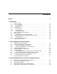
Futurebus+ Bus Support 15.2 Futurebus+ Address Space Figure 15–1 32 Bit Futurebus+ Address Space 32 bit Futurebus+ address space 0000 0000 A32 Memory Space 0000 0000 0000 0000 Use A32 Equivalent EFFF FFFF F000 0000 CSRs FFFF FFFF 0000 0000 EFFF FFFF 0000 0000 F000 0000 A64 Memory Space FFFF FFFF FFFF FFFF ZK−6726A−GE 15.3 Futurebus+ CSR Addressing Futurebus+ requires that all nodes support A32 addressing. While referencing CSRs only 32 bit addressing should be used.
Futurebus+ Bus Support 15.
Futurebus+ Bus Support 15.3 Futurebus+ CSR Addressing Core, Futurebus+ Dependent, ROM, and Initial Units Space. The CSR Core space is defined by IEEE 1212 (CSR Architecture). Futurebus+ Dependent space is defined by IEEE 896.2 (Physical Layer and Profile). ROM space is defined by both IEEE 1212 and 896.2. Initial Units Space is vendor defined. [LIB.LIS]FBUSDEF.SDL defines symbolic register offsets for the 4KB initial node space. 15.
Futurebus+ Bus Support 15.5 Futurebus+ Register Access 15.5 Futurebus+ Register Access On both the DEC 10000/7000 and DEC 4000 platforms, access to Futurebus+ CSR space is accomplished through hardware I/O mailboxes or the device register access routines described in Appendix A. A driver uses the standard register access routines provided by OpenVMS/AXP to accomplish a register access. 15.5.
Futurebus+ Bus Support 15.5 Futurebus+ Register Access An example call to IOC$CRAM_CMD is as follows: status = ioc$cram_cmd(cramcmd$k_rdlong32, command index */ 4, /* byte offset */ adp_address, cram_address); /* The COMMAND field bit patterns are stored in a table pointed to by field ADP$PS_COMMAND_TBL in the Futurebus+ ADP. IOC$CRAM_CMD uses the command index to find the proper COMMAND field bit pattern, and copies the command field bits to CRAM$L_COMMAND.
Futurebus+ Bus Support 15.7 Futurebus+ Interrupts Figure 15–5 Futurebus+ Target Register Fbus Bridge Fbus Host System Interrupt Request registers implemented on Fbus Bridge Fbus Adapter Interrupt Target Interrupt Vector Interrupt Target programmed with Interrupt Request register address during driver initialization. Interrupt Vector programmed with vector during driver initialization. Fbus Adapter interrupts host by writing Interrupt Vector contents to Interrupt Request register on bridge.
Futurebus+ Bus Support 15.8 Futurebus+ System Routines 15.8 Futurebus+ System Routines The Initial Node Space base address of a Futurebus+ adapter is determined by the backplane slot into which the adapter is installed. For most adapters, device control functions can be accomplished through registers located in the adapter Initial Unit Space. However, some adapters require additional Futurebus+ address space for their operation.
Futurebus+ Bus Support 15.9 Configuring a Futurebus+ Adapter 15.9 Configuring a Futurebus+ Adapter Manual configuration of adapters is very similar across platforms and buses. There are some bus-specific differences, usually in the format of the base CSR address and in the specification of the interrupt vector(s). The SYSMAN utility is used to manually configure adapters. In order to manually configure a Futurebus+ adapter, the first step is to issue the SYSMAN IO SHOW BUS command.
Futurebus+ Bus Support 15.9 Configuring a Futurebus+ Adapter Figure 15–6 System Control Block System Control Block SCB offset 0 EXE$GL_SCB 10 20 . . . . . . 800 1 810 1 820 . . . . . . . . . 1FE0 1 1FF0 0 EXE$GL_SCB_RESERVATION I/O interrupt vectors start at SCB offset 800 (hex) EXE$GL_SCB_RESERVATION points to a bit− vector which indicates which SCB entries in the I/O portion of the SCB are in use. If bit 0 of the reservation vector is set, then SCB offset 800 is in use.
Futurebus+ Bus Support 15.9 Configuring a Futurebus+ Adapter Figure 15–7 System Control Block System Control Block SCB offset 0 10 20 . . . . . . 800 OpenVMS/AXP vector assignments 810 820 . . . . . . . . . 1FE0 1FF0 Manually configured Futurebus+ adapter vector assignments ZK−6732A−GE Note that interrupt vectors assigned using SYSMAN IO CONNECT commands will not be reflected in the SCB Reservation bitmap. 15.
Futurebus+ Bus Support 15.10 Futurebus+ Bus Probing During Booting a driver from vendor Y–the spec_id identifies the manufacturer that supplies the driver (vendor Y, in this example). If a spec_id is found, INI$IOMAP uses it rather than the vendor_id to identify the board manufacturer. INI$IOMAP also searches the node ROM space for one of MODULE_SW_VERSION, NODE_SW_ VERSION, or UNIT_SW_VERSION (again, the Futurebus+ specifications claim that only one of these locations should be present in the ROM).
Futurebus+ Bus Support 15.11 Futurebus+ on DEC 4000 Figure 15–8 DEC 4000 Futurebus+ Address Space Futurebus+ A32 Space DEC 4000 System Memory 0000 0000 0000 0000 2 GB 7FFF FFFF 8000 0000 EFFF FFFF F000 0000 FFFF FFFF Max size 2 GB 7FFF FFFF CSR space ZK−6733A−GE The DEC 4000 I/O module responds as a Futurebus+ slave to A32 addresses in the range 0000 0000 to 7FFF FFFF. A32 transfers in this address range will be passed to system memory by the I/O module.
Futurebus+ Bus Support 15.
Futurebus+ Bus Support 15.12 Futurebus+ on DEC 10000/7000 As a Futurebus+ master, the Flag can generate A32 and A64 address width transactions, and D32 and D64 data width transactions. As a Futurebus+ slave, the Flag accepts both A32 and A64 address width transactions, and D32 and D64 data width transactions. 15.12.2 DEC 10000/7000 Futurebus+ Address Space The DEC 10000/7000 system supports a 40 bit (1 TB) memory address space.
Futurebus+ Bus Support 15.12 Futurebus+ on DEC 10000/7000 Figure 15–11 Futurebus+ A64 Space Futurebus+ A64 Space 0000 0000 0000 0000 DEC 10000/7000 System Memory 00 0000 0000 Use A32 equivalent address 0000 00FF EFFF FFFF 0000 0000 F000 0000 0000 00FF FFFF FFFF FF FFFF FFFF A64 available memory space FFFF FFFF FFFF FFFF ZK−6736A−GE The Flag responds as a Futurebus slave to A64 transactions from 0000 0000 F000 0000 to 0000 00FF FFFF FFFF and passes the transfer to DEC 10000/7000 system memory.
Futurebus+ Bus Support 15.
A Device Support Bus Routines This appendix provides more information about some of the device support bus routines described in this manual.
OpenVMS System Routines Called by OpenVMS AXP Device Drivers IOC$ALLOC_CNT_RES IOC$ALLOC_CNT_RES Allocates the requested number of items of a counted resource. Module ALLOC_CNT_RES Format IOC$ALLOC_CNT_RES crab ,crctx Context IOC$ALLOC_CNT_RES conforms to the OpenVMS AXP calling standard. Its caller must be executing at fork IPL, holding the corresponding fork lock.
OpenVMS System Routines Called by OpenVMS AXP Device Drivers IOC$ALLOC_CNT_RES SS$_BADPARAM SS$_INSFMAPREG Request count was greater than the total number of items managed by the CRAB or the total number of items defined by a bounded request. This status is also returned if the lower bound of the request (CRCTX$L_LOW_BOUND) is greater than the upper bound (CRCTX$L_UP_BOUND). Insufficient resources to satisfy request.
OpenVMS System Routines Called by OpenVMS AXP Device Drivers IOC$ALLOC_CNT_RES The number of the first resource item granted to the caller is placed in CRCTX$L_ITEM_NUM and CRCTX$V_ITEM_VALID is set in CRCTX$L_ FLAGS. • If this allocation attempt fails, saves the current values of R3, R4, and R5 in the CRCTX fork block. IOC$ALLOC_CNT_RES writes a –1 to CRCTX$L_ ITEM_NUM, and inserts the CRCTX in the resource-wait queue (headed by CRAB$L_WQFL). It then returns SS$_INSFMAPREG status to its caller.
OpenVMS System Routines Called by OpenVMS AXP Device Drivers IOC$ALLOC_CNT_RES IOC$ALLOC_CNT_RES never stalls a high-priority counted resource request or places its CRCTX in a resource-wait queue. Rather, it attempts to allocate the requested number of resource items immediately. If IOC$ALLOC_CNT_RES cannot grant the requested number of items, it returns SS$_INSFMAPREG status to its caller.
OpenVMS System Routines Called by OpenVMS AXP Device Drivers IOC$ALLOC_CRAB IOC$ALLOC_CRAB Allocates and initializes a counted resource allocation block (CRAB). Module ALLOC_CNT_RES Format IOC$ALLOC_CRAB item_cnt ,req_alloc_gran ,crab_ref Context IOC$ALLOC_CRAB conforms to the OpenVMS AXP calling standard. Because IOC$ALLOC_CRAB calls EXE$ALONONPAGED to allocate sufficient memory for a CRAB, its caller cannot be executing above IPL$_POOL.
OpenVMS System Routines Called by OpenVMS AXP Device Drivers IOC$ALLOC_CRAB Return Values SS$_BADPARAM SS$_NORMAL SS$_INSFMEM Specified allocation granularity is larger than the specified item count. The routine completed successfully. Memory allocation request failed. Description A driver calls IOC$ALLOC_CRAB to allocate a counted resource allocation block (CRAB) that describes a counted resource.
OpenVMS System Routines Called by OpenVMS AXP Device Drivers IOC$ALLOC_CRCTX IOC$ALLOC_CRCTX Allocates and initializes a counted resource context block (CRCTX). Module ALLOC_CNT_RES Format IOC$ALLOC_CRCTX crab ,crctx_ref ,[fleck_index] Context IOC$ALLOC_CRCTX conforms to the OpenVMS AXP calling standard. Because IOC$ALLOC_CRCTX calls EXE$ALONONPAGED to allocate sufficient memory for a CRCTX, its caller cannot be executing above IPL$_POOL.
OpenVMS System Routines Called by OpenVMS AXP Device Drivers IOC$ALLOC_CRCTX Description A driver calls IOC$ALLOC_CRCTX to allocate a CRCTX to describe a specific request for a given counted resource, such as a set of map registers. The driver subsequently uses the CRCTX as input to IOC$ALLOC_CNT_RES to allocate a given set of the objects managed as a counted resource. IOC$ALLOC_CRCTX calls EXE$ALONONPAGED to allocate the CRCTX.
OpenVMS System Routines Called by OpenVMS AXP Device Drivers IOC$ALLOCATE_CRAM IOC$ALLOCATE_CRAM Allocates a controller register access mailbox. Module CRAM-ALLOC Macro DPTAB (ucb_crams and idb_crams arguments) CRAM_ALLOC Format IOC$ALLOCATE_CRAM cram [,idb] [,ucb] [,adp] Context IOC$ALLOCATE_CRAM conforms to the OpenVMS AXP calling standard.
OpenVMS System Routines Called by OpenVMS AXP Device Drivers IOC$ALLOCATE_CRAM Address of ADP for device. Returns VMS Usage: type: access: mechanism: cond_value longword_unsigned longword (unsigned) write only—by value Status indicating the success or failure of the operation. Return Values SS$_NORMAL SS$_INSFARG CRAM has been successfully allocated.
OpenVMS System Routines Called by OpenVMS AXP Device Drivers IOC$CANCEL_CNT_RES IOC$CANCEL_CNT_RES Cancels a thread that has been stalled waiting for a counted resource. Module ALLOC_CNT_RES Format IOC$CANCEL_CNT_RES crab ,crctx [,resume_flag] Context IOC$CANCEL_CNT_RES conforms to the OpenVMS AXP calling standard. Its caller must be executing at fork IPL, holding the corresponding fork lock.
OpenVMS System Routines Called by OpenVMS AXP Device Drivers IOC$CANCEL_CNT_RES Return Values SS$_NORMAL SS$_BADPARAM The routine completed successfully. The specified CRCTX was not found in the CRAB wait queue. Description IOC$CANCEL_CNT_RES cancels a thread that has been stalled waiting for a counted resource. The resource request is described in the CRCTX structure; the counted resource itself is described in the CRAB.
OpenVMS System Routines Called by OpenVMS AXP Device Drivers IOC$CRAM_CMD IOC$CRAM_CMD Generates values for the command, mask, and remote I/O interconnect address fields of the hardware I/O mailbox that are specific to the interconnect that is the target of the mailbox operation, inserting these values into the indicated mailbox, buffer, or both.
OpenVMS System Routines Called by OpenVMS AXP Device Drivers IOC$CRAM_CMD Command Index Description CRAMCMD$K_WTBYTE32 CRAMCMD$K_RDQUAD64 CRAMCMD$K_RDLONG64 CRAMCMD$K_RDWORD64 CRAMCMD$K_RDBYTE64 CRAMCMD$K_WTQUAD64 CRAMCMD$K_WTLONG64 CRAMCMD$K_WTWORD64 CRAMCMD$K_WTBYTE64 Byte write in 32-bit space Quadword read in 64 bit space Longword read in 64 bit space Word read in 64 bit space Byte read in 64 bit space Quadword write in 64 bit space Longword write in 64 bit space Word write in 64 bit space Byte write
OpenVMS System Routines Called by OpenVMS AXP Device Drivers IOC$CRAM_CMD Return Values SS$_NORMAL SS$_BADPARAM SS$_INSFARG The calculated command, mask, and remote bus address values have been written to the CRAM and/or the specified buffer.
OpenVMS System Routines Called by OpenVMS AXP Device Drivers IOC$CRAM_IO IOC$CRAM_IO Queues the hardware I/O mailbox defined within a controller register access mailbox (CRAM) to the mailbox pointer register (MBPR) and awaits the completion of the mailbox transaction. Module [SYSLOA]CRAM-IO Macro CRAM_IO Format IOC$CRAM_IO cram Context IOC$CRAM_IO conforms to the OpenVMS AXP calling standard. It acquires no spin locks and leaves IPL unchanged.
OpenVMS System Routines Called by OpenVMS AXP Device Drivers IOC$CRAM_IO SS$_TIMEOUT Mailbox operation did not complete in mailbox transaction timeout interval. Description IOC$CRAM_IO performs an entire hardware I/O mailbox transaction from the queuing of the hardware I/O mailbox to the MBPR to the transaction’s completion. A call to IOC$CRAM_IO is the equivalent of independent calls to IOC$CRAM_QUEUE and IOC$CRAM_WAIT.
OpenVMS System Routines Called by OpenVMS AXP Device Drivers IOC$CRAM_QUEUE IOC$CRAM_QUEUE Queues the hardware I/O mailbox defined within a controller register access mailbox (CRAM) to the mailbox pointer register (MBPR). Module [SYSLOA]CRAM-IO Macro CRAM_QUEUE Format IOC$CRAM_QUEUE cram Context IOC$CRAM_QUEUE conforms to the OpenVMS AXP calling standard. It acquires no spin locks and leaves IPL unchanged. After queuing the request, IOC$CRAM_QUEUE returns to its caller.
OpenVMS System Routines Called by OpenVMS AXP Device Drivers IOC$CRAM_QUEUE Description IOC$CRAM_QUEUE initiates an I/O operation to a device in remote I/O space by writing the physical address of the hardware I/O mailbox portion of a CRAM to the MBPR. Prior to calling IOC$CRAM_QUEUE, a driver typically calls IOC$CRAM_CMD to insert a command, mask, and remote interconnect address into the hardware I/O mailbox portion of the CRAM.
OpenVMS System Routines Called by OpenVMS AXP Device Drivers IOC$CRAM_WAIT IOC$CRAM_WAIT Awaits the completion of a hardware I/O mailbox transaction to a tightly-coupled I/O interconnect. Module [SYSLOA]CRAM-IO Macro CRAM_WAIT Format IOC$CRAM_WAIT cram Context IOC$CRAM_WAIT conforms to the OpenVMS AXP calling standard. It acquires no spin locks and leaves IPL unchanged. After queuing the request, IOC$CRAM_ WAIT returns to its caller.
OpenVMS System Routines Called by OpenVMS AXP Device Drivers IOC$CRAM_WAIT SS$_INSFARG SS$_TIMEOUT No argument supplied in call. Mailbox operation did not complete in mailbox transaction timeout interval.
OpenVMS System Routines Called by OpenVMS AXP Device Drivers IOC$DEALLOC_CNT_RES IOC$DEALLOC_CNT_RES Deallocates the requested number of items of a counted resource. Module DEALLOC_CNT_RES Format IOC$DEALLOC_CNT_RES crab ,crctx Context IOC$DEALLOC_CNT_RES conforms to the OpenVMS AXP calling standard. Its caller must be executing at fork IPL, holding the corresponding fork lock. Arguments crab VMS Usage: type: access: mechanism: address longword (unsigned) read only by reference Address of CRAB.
OpenVMS System Routines Called by OpenVMS AXP Device Drivers IOC$DEALLOC_CNT_RES Description IOC$DEALLOC_CNT_RES deallocates a requested number of items of a counted resource. The resource request is described in the CRCTX structure; the counted resource itself is described in the CRAB. After deallocating the items, IOC$DEALLOC_CNT_RES attempts to restart any waiters for the resource. IOC$DEALLOC_CNT_RES performs the following tasks: 1. It examines CRCTX$V_ITEM_VALID in CRCTX$L_FLAGS.
OpenVMS System Routines Called by OpenVMS AXP Device Drivers IOC$DEALLOC_CRAB IOC$DEALLOC_CRAB Deallocates a counted resource allocation block (CRAB). Module ALLOC_CNT_RES Format IOC$DEALLOC_CRAB crab Context IOC$DEALLOC_CRAB conforms to the OpenVMS AXP calling standard. Because IOC$DEALLOC_CRAB calls EXE$DEANONPAGED, its caller cannot be executing above IPL$_SYNCH. Arguments crab VMS Usage: type: access: mechanism: address longword (unsigned) read only by reference Address of CRAB to be deallocated.
OpenVMS System Routines Called by OpenVMS AXP Device Drivers IOC$DEALLOC_CRCTX IOC$DEALLOC_CRCTX Deallocates a counted resource context block (CRCTX). Module ALLOC_CNT_RES Format IOC$DEALLOC_CRCTX crctx Context IOC$DEALLOC_CRCTX conforms to the OpenVMS AXP calling standard. Because IOC$DEALLOC_CRCTX calls EXE$DEANONPAGED, its caller cannot be executing above IPL$_SYNCH.
OpenVMS System Routines Called by OpenVMS AXP Device Drivers IOC$DEALLOCATE_CRAM IOC$DEALLOCATE_CRAM Deallocates a controller register access mailbox. Module CRAM-ALLOC Macro CRAM_DEALLOC Format IOC$DEALLOCATE_CRAM cram Context IOC$DEALLOCATE_CRAM conforms to the OpenVMS AXP calling standard. Its caller must be executing at or below IPL 8 and must not hold spin locks ranked higher than IO_MISC.
OpenVMS System Routines Called by OpenVMS AXP Device Drivers IOC$MAP_IO IOC$MAP_IO IOC$MAP_IO maps I/O bus physical address space into an address region accessible by the processor. The caller of this routine can express the mapping request in terms of the bus address space without regard to address swizzle space, dense space, or sparse space. IOC$MAP_IO is supported on PCI, EISA, TURBOchannel, and Futurebus+ systems. It is not supported on XMI systems.
OpenVMS System Routines Called by OpenVMS AXP Device Drivers IOC$MAP_IO Request mapping in a platform address space that corresponds to bus memory space and provides coarse access granularity. IOC$K_BUS_DENSE_SPACE is suitable for mapping device memory buffers such as graphics frame buffers. In IOC$K_BUS_DENSE_SPACE, there must be no side effects on reads and it may be possible for the processor to merge writes. Thus you should not map device registers in dense space. iohandle Pointer to a 64 bit cell.
OpenVMS System Routines Called by OpenVMS AXP Device Drivers IOC$READ_IO IOC$READ_IO Reads a value from a previously mapped location in I/O address space. This routine requires that the I/O space to be accessed has been previously mapped by a call to IOC$MAP_IO. IOC$READ_IO is supported on PCI, EISA, TURBOchannel, and Futurebis+ systems. It is not supported on XMI systems.
OpenVMS System Routines Called by OpenVMS AXP Device Drivers IOC$READ_IO SS$_UNSUPPORTED A transaction length not supported by this bus or platform.
OpenVMS System Routines Called by OpenVMS AXP Device Drivers IOC$UNMAP_IO IOC$UNMAP_IO Unmaps a previously mapped I/O address space, returning the IOHANDLE and the PTEs to the system. The caller’s quadword cell containing the IOHANDLE is cleared.
OpenVMS System Routines Called by OpenVMS AXP Device Drivers IOC$WRITE_IO IOC$WRITE_IO Writes a value to a previously mapped location in I/O address space. IOC$WRITE_IO requires that the I/O space to be accessed has been previously mapped by a call to IOC$MAP_IO. Description The routine prototype is as follows: int ioc$write_io (ADP uint64 int int void *adp, *iohandle, offset, length, *write_data) Inputs adp Address of bus ADP. Driver can get this from IDB$PS_ADP.
B Sample Driver Written in C This appendix contains a sample driver written in C and a command procedure for compiling and linking the driver. B.1 LRDRIVER Example The LRDRIVER is for the parallel output port of the VL82C106 Combo chip on an ISA option card for the DEC 2000 Model 300 AXP system. You can obtain the most current version of this driver from the SYS$EXAMPLES directory.
Sample Driver Written in C B.1 LRDRIVER Example /* Define system data structure types and constants */ #include #include #include #include #include #include #include #include #include #include #include #include #include #include #include #include #include #include #include #include #include #include #include #include
Sample Driver Written in C B.1 LRDRIVER Example /* Define the line printer port CSR offsets. * Note that the unit initialization routine determines if this unit is * associated with a VL82C106 on system bus or on an ISA option card. * Note also that due to the byte-laned I/O space, data read from the ISA * LPS register (byte offset 1) must be shifted right 1 byte, and data read * from the LPC register (byte offset 2) must be shifted right 2 bytes.
Sample Driver Written in C B.
Sample Driver Written in C B.1 LRDRIVER Example /* * DRIVER$INIT_TABLES - Initialize Driver Tables * * Functional description: * * This routine completes the initialization of the DPT, DDT, and FDT * structures. If a driver image contains a routine named DRIVER$INIT_TABLES * then this routine is called once by the $LOAD_DRIVER service immediately * after the driver image is loaded or reloaded and before any validity checks * are performed on the DPT, DDT, and FDT.
Sample Driver Written in C B.
Sample Driver Written in C B.1 LRDRIVER Example * None. * * Environment: * * Kernel mode, system context, IPL may be as high as 31 and may not be * altered. * */ void lr$struc_init (CRB *crb, DDB *ddb, IDB *idb, ORB *orb, LR_UCB *ucb) { /* Initialize the fork lock and device IPL fields */ ucb->ucb$r_ucb.ucb$b_flck = SPL$C_IOLOCK8; ucb->ucb$r_ucb.
Sample Driver Written in C B.1 LRDRIVER Example * ucb Pointer to the unit control block that is to be initialized. * * Output parameters: * * None. * * Return value: * * None. * * Environment: * * Kernel mode, system context, IPL may be as high as 31 and may not be * altered. * */ void lr$struc_reinit (CRB *crb, DDB *ddb, IDB *idb, ORB *orb, LR_UCB *ucb) { extern DDT driver$ddt; /* Setup the pointer from our DDB in the I/O database to the driver * dispatch table that’s within this driver image.
Sample Driver Written in C B.1 LRDRIVER Example * * Environment: * * Kernel mode, system context, IPL 31. */ int lr$unit_init (IDB *idb, LR_UCB *ucb) { static int combo_initialized = 0; CRAM *cram; ADP *adp; int isa_io_addr; int device_data; int status; /* First unit is on system bus */ /* Slot I/O address if ISA option */ /* Data from or for CRAM */ #if defined DEBUG /* If a debug version of this driver is being built then invoke the loaded * system debugger.
Sample Driver Written in C B.1 LRDRIVER Example cram = cram->cram$l_flink; cram->cram$v_der = 1; ucb->ucb$ps_cram_lcw = cram; ioc$cram_cmd (CRAMCMD$K_WTLONG32, LR_COMBO_LCW, adp, cram, 0); } else { /* This unit is for VL82C106 on ISA bus */ /* Get and validate the ISA IRQ */ status = ioc$node_data (ucb->ucb$r_ucb.
Sample Driver Written in C B.1 LRDRIVER Example /* Mark the device as "on line" and ready to accept I/O requests */ ucb->ucb$r_ucb.ucb$v_online = 1; return SS$_NORMAL; } /* * LR$SETMODE - FDT Routine for Set Mode and Set Characteristics * * Functional description: * * This routine is called by the FDT dispatcher in the $QIO system service * to process set mode and set characteristics functions. This FDT routine * completes the I/O request without sending it to the driver start I/O * routine.
Sample Driver Written in C B.1 LRDRIVER Example /* The caller passes the address of their setmode buffer in the $QIO P1 * parameter. */ setmode_bufp = (SETMODE_BUF *) irp->irp$l_qio_p1; /* Assure that the caller’s setmode buffer is readable by the caller. * If not, abort the I/O request now with an ACCVIO status and return * back to the FDT dispatcher in the $QIO system service.
Sample Driver Written in C B.1 LRDRIVER Example * irp Pointer to I/O request packet * pcb Pointer process control block * ucb Pointer to unit control block * ccb Pointer to channel control block * * Output parameters: * * None. * * Return value: * * status SS$_FDT_COMPL * * Environment: * * Kernel mode, user process context, IPL 2. */ int lr$write (IRP *irp, PCB *pcb, LR_UCB *ucb, CCB *ccb) { /* Define a structure type for the carraige control information that * is returned from exe_std$carriage.
Sample Driver Written in C B.1 LRDRIVER Example /* If this is not a "pass all" request, then interpret the $QIO P4 * carriage control parameter. Adjust the required system buffer packet * size by the prefix and suffix counts plus room of data expansion. * Currently, the only expansion possible is an extra CR in the prefix * and suffix characters if "new line" was specified.
Sample Driver Written in C B.1 LRDRIVER Example /* Expand the suffix carriage control into the allocated system * buffer. If the carriage control count is non-zero and the * carriage control character is 0, this means "new line." Output * an initial CR, then the counted number of LFs.
Sample Driver Written in C B.1 LRDRIVER Example * * Environment: * * Kernel mode, system context, fork IPL, fork lock held. */ void lr$startio (IRP *irp, LR_UCB *ucb) { int orig_ipl; /* Adjust ucb$l_svapte such that it points to the start of the data in * the system buffer packet. */ ucb->ucb$r_ucb.ucb$l_svapte = (char *) ucb->ucb$r_ucb.ucb$l_svapte + sizeof(SYSBUF_HDR); /* Acquire the device lock, raise IPL, saving original IPL */ device_lock (ucb->ucb$r_ucb.
Sample Driver Written in C B.1 LRDRIVER Example * * Environment: * * Kernel mode, system context, device IPL, device lock held. */ static int lr$send_char_dev (LR_UCB *ucb) { int device_data; char *sys_datap; /* Data from or for CRAM */ /* Pointer to next byte in buffer packet */ /* Set the Port Control Register. * Set the INIT_OFF bit to disable the "INIT" signal. Set the IRQ_EN bit * to enable interrupts.
Sample Driver Written in C B.1 LRDRIVER Example /* * LR$INTERRUPT - Interrupt Service Routine * * Functional description: * * This is the interrupt service routine for the parallel line printer * port. This routine is called by the system interrupt dispatcher. * * This routine will attempt to send the next character to the device * until either there are no more characters left or the I/O is canceled.
Sample Driver Written in C B.1 LRDRIVER Example /* If there are characters left and the I/O has not been cancelled * then attempt to send the next character. There is no need to check * the status since the interrupt timeout will expire if the device is * not ready. Otherwise, queue the I/O done fork routine that was * setup via wfikpch. */ if (ucb->ucb$r_ucb.ucb$l_bcnt > 0 && ! ucb->ucb$r_ucb.ucb$v_cancel) { lr$send_char_dev (ucb); } else { ucb->ucb$r_ucb.ucb$v_int = 0; ucb->ucb$r_ucb.
Sample Driver Written in C B.1 LRDRIVER Example /* If the request was cancelled or timed out of its own accord then * set the status accordingly. */ if (ucb->ucb$r_ucb.ucb$v_cancel) { status = SS$_ABORT; } else if (ucb->ucb$r_ucb.
Sample Driver Written in C B.1 LRDRIVER Example /* * LR$CHECK_READY_FORK - Periodic Check for Device Ready * * Functional description: * * This routine performs a once-a-second check of the readiness of the * device to resume output. While the device remains offline this fork * routine reschedules itself via the fork wait queue. When the device * is ready to resume, the next character is sent and the remainder of * the output is done by the interrupt service routine.
Sample Driver Written in C B.1 LRDRIVER Example /* If we successfully sent a character to the device then we’re back in * business. Set up a wait for the completion of the I/O via wfikpch * just like our start I/O routine. Wfikpch will restore the device lock * and restore IPL. But first, clear the offline count and set the offline * message interval to its initial value. And, return from this routine.
Sample Driver Written in C B.2 LRDRIVER.COM B.2 LRDRIVER.COM The LRDRIVER.COM command procedure compiles and links the LRDRIVER.C device driver. $ SET NOON $ SAVED_VFY = F$VERIFY("NO","NO") $ ON CONTROL_Y THEN GOTO QUIT $ SET VERIFY=(PROCEDURE,NOIMAGE) $! $! LRDRIVER.COM $! This is the compile and link procedure for the example device driver $! LRDRIVER.C.
Sample Driver Written in C B.2 LRDRIVER.COM ! This cluster is used to control the order of symbol resolution. All ! psects must be collected off of this cluster so that it generates ! no image sections. ! CLUSTER=VMSDRIVER,,,! ! Start with the driver module ! OBJ$:LRDRIVER.OBJ,! ! Next process the private interfaces. (Only include BUGCHECK_CODES if ! used by the driver module).
Sample Driver Written in C B.2 LRDRIVER.COM ! ! Use a COLLECT statement to implicitly declare the NONPAGED_DATA_PSECTS ! cluster. Mark the cluster with the RESIDENT attribute so that the image ! section produced is nonpaged. Collect all the data psects into the cluster.
Index A ADP (adapter control block), 1–5 Alternate start I/O routine address, 4–3 AST (asynchronous system trap) special kernel-mode, 5–9 AUTOCONFIGURE command in System Management utility (SYSMAN), 10–4 B Buffer allocating, 1–10, 5–8 data area, 5–8 deallocating, 5–9 format, 5–8 header area, 5–8 locking, 1–10, 4–5 size, 5–8 storing address of, 5–8 testing accessibility of, 5–8 Buffered data path releasing, 8–2 Buffered function mask, 4–4, 4–5 Buffered I/O, 1–9, 1–10 FDT routines for, 5–7 to 5–9 functions,
Device controller data channel obtaining ownership of, 6–2 releasing, 6–4, 8–2 requesting, 6–2 unavailability, 6–2 Device driver, 1–1 asynchronous nature, 1–1, 1–7 to 1–8 components, 1–2 to 1–3 configuring, 10–10 context, 1–6 to 1–8 entry points, 1–2, 4–3, 4–4 example, B–1 to B–22 flow, 1–7 to 1–8 functions, 1–1 to 1–2 loading, 4–1 maximum number of supported units, 4–2 program sections, 4–3 showing information, 10–10 suspending, 6–4 synchronization methods used by, 1–6 Device interrupt, 1–4, 7–1 disabling,
FDT completion routine, 5–1 FDT completion routines, 5–5 to 5–7 FDT processing calling sequence, 5–2 to 5–3 FDT routine, 1–2, 1–9 to 1–10 allocating system buffer in, 5–8 context, 5–2 creating, 5–1 to 5–9 for buffered I/O, 5–7 to 5–9 for direct I/O, 5–4, 5–7 register usage, 5–2 system-provided, 5–3 to 5–9 upper-level, 4–5, 5–1, 5–2 to 5–3 FDT support routine, 5–1 FDT_ACT macro, 4–5 FDT_BUF macro, 4–5 FDT_INI macro, 4–5 Feedback on documentation, sending to Digital, iii Fork block, 1–4, 1–7, 8–1 Fork context
IOC_STD$INITIATE, 6–1 IOC_STD$PRIMITIVE_REQCHANL, 6–2 IOC_STD$REQCOM, 6–18–3 $IODEF macro, 4–6 IOFORK macro, 7–2, 8–1 IOSB (I/O status block), 8–2 IPL$_IOPOST, 8–3 IPL$_MAILBOX, 8–6 IPL$_POWER, 6–3, 6–4 IPL$_TIMERFORK, 8–3, 8–4 IPL (interrupt priority level), 1–6 IRP$L_BCNT, 6–2 writing, 5–8 IRP$L_BOFF, 5–8 IRP$L_MEDIA, 8–3 IRP$L_STS for read function, 5–8 IRP$L_SVAPTE, 6–2 for buffered I/O, 5–8, 5–9 IRP$V_FUNC, 5–8, 5–9 IRP$W_BOFF, 6–2 IRP$W_FUNC, 6–3 IRP$W_STS for read function, 5–9 for write function, 5–
SHOW BUS command in System Management utility (SYSMAN), 10–9 SHOW DEVICE command in System Management utility (SYSMAN), 10–10 SHOW PREFIX command in System Management utility (SYSMAN), 10–12 Software timer interrupt service routine, 8–3 Solicited interrupt See Device interrupt Spinlock, 1–6 SS$_ABORT, 8–5 Stack device driver use of, 6–1 Start I/O routine address, 4–3 Start-I/O routine, 1–3 context, 6–1, 6–2 kernel process, 4–4 register usage, 6–1 synchronization requirements, 6–3 transferring control to, 6–
W Wait for interrupt macro See WFIKPCH macro, WFIRLCH macro WFIKPCH macro, 6–3, 6–4, 8–7 WFIRLCH macro, 6–3, 6–4 Write function FDT routine for, 5–4 Index–6