
Installation guide
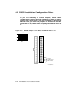
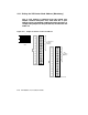
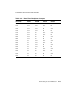
Refer to Figure 4–4 to determine which jumper corresponds to which
backplane pin. The XMI backplane pin numbering is exactly the same as
the VAXBI backplane pin numbering. There are 29 possible pins that may
need jumpers on the backplane, in sections D and E. The corresponding
jumpers are denoted W1 through W30, with W9 being reserved.
The module functions that must be modified by jumper placement are the
following:
Set CI port address (mandatory)
Set Quiet Slot DELTA Time to 10 (mandatory)
In addition, you can modify the following characteristics:
Boot time
Disable arbitration
Extend header
Cluster size
Extend ACK timeout
The general procedure for installing jumpers is as follows:
1. Open the rear cabinet door.
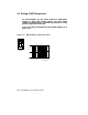
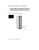
2. Find the XMI backplane slot corresponding to the CIXCD module. The
internal cables are connected to the pins on the leftmost section of the
module as seen from the rear. The jumpers are installed on the pins of
the rightmost segment of the module.
3. Insert jumpers between backplane pins to set the desired module
parameters. Specific pins for desired parameters are described in
sections that follow.
4. Close the cabinet door.
You cannot use the default configuration. You must change the Quiet Slot
DELTA Time to 10. The default configuration for a system with no jumpers
installed would be:
CI Node Address = 0
Quiet Slot DELTA Time is at 7,
and must be set to 10 on all systems in the cluster
Boot Time = 1500 seconds
Normal CI Arbitration
Normal Header systems in the cluster
Cluster Size = 16
Short ACK Timeout
Connecting to a CI VAXcluster 4–7