
Installation guide
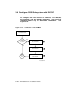
1. XMI Node Number
Locate the XMI slot of the KFMSA by either looking in the XMI card
cage, reading the XMI module use label on the cabinet frame by the card
cage, or at the console prompt, issuing a SHOW CONFIGURATION
command. The XMI node number and physical slot number are the
same.
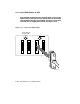
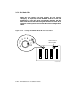
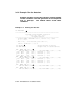
2. DSSI Bus Number
Each KFMSA module has two separate DSSI buses (ports) cabled from
XMI backplane sections D and E. The cable from section D (upper
section) is designated as bus 1, and the cable from section E is bus
2. Each bus presents a discrete set of registers to the host. For
communication to occur, the host software must identify which DSSI
bus is attached to which ISE. Use the color-coded labels at each
connector end of a cable to make maintenance easier. Record the label
colors on the configuration sheet.
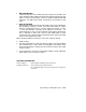
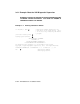
When attaching cables to the SF2xx, at the rear of the SF cabinet:
1. Open the door.
2. For each populated bus, install one external cable to one of the KFMSA
disk controller ports. DSSI cables are packaged in the bottom of the
SF2xx storage cabinet. Tighten the two screws that secure each cable
to the I/O panel.
3. If the system has more than one KFMSA adapter, install additional
DSSI cables to the I/O panel, as above.
FOR MORE INFORMATION
Primary reference: KFMSA Module Installation and User Manual
Secondary references: SF2xx Storage Array Installation Guide
SF7x Storage Enclosure and SF2xx Storage Array Cabinet Ser-
vice Guide
Connecting to a DSSI Subsystem 3–27