
Installation guide
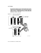

The DSSI buses are configured physically by the cable. Check your cables
before beginning installation. If you need additional cables, see Table 3–5.
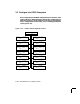
The overall physical bus length is limited. Therefore, systems and devices
on the DSSI bus must reside close to each other. One external DSSI cable is
required for each bus connection between systems; two cables are required
to connect two systems and an SF2xx cabinet.
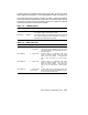
Table 3–5: KFMSA Options
Option Board P/N Contents
KFMSA-AA T2036-AA The KFMSA adapter with bus termination on the mod-
ule; supports single- and dual-host systems.
KFMSA-BA T2036-BA The KFMSA adapter with removable termination on the mod-
ule; supports single-host when termination is present, or
multi-host when termination is removed.
Table 3–6: DSSI Cable Kits
P/N Qty—Length Function
CK-SF200-LM 1 108" (2.7m)
1 70" (1.8m)
For VAX to SF connections. Contains two ca-
bles (BC21Q-09 and BC21R-5L). One kit is re-
quired for each DSSI bus used (maximum of two
kits per KFMSA).
CK-KFMSA-LJ 2 48" (1.21m) Internal cable set, connecting XMI back-
plane at KFMSA adapter to the I/O bulk-
head on the host system. Used when the
host is the end node of a DSSI subsys-
tem.
CK-KFMSA-LN 2 48" (1.21m) Internal cable set, connecting XMI back-
plane at KFMSA adapter to the I/O bulk-
head on tri-host systems. Used when the
host is not an end node of a DSSI subsys-
tem.
CK-KFMSA-LR 1 120" (3.04m)
1 48" (1.21m)
Internal cable set, connecting TF85 tape con-
troller and the KFMSA XMI backplane connec-
tions to the host I/O bulkhead.
Connecting to a DSSI Subsystem 3–23