
Installation guide
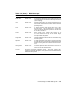
The KFMSA runs a self-test during power-up and reports results to the
system self-test display. The yellow LED on the KFMSA lights to indicate
that self-test passed.
If a KFMSA fails self-test, check the diagnostic LEDs on the board. Two
sets of four red LEDs report status for each of the logical ports associated
with the two physical buses. See the KFMSA Module Installation and
User Manual chapter, Power-On Self-Test, for details on the KFMSA LED
readout.
In addition to the KFMSA adapter self-test status, each ISE has its own
self-test. To check status of ISEs, for disks, check the status LEDs on the
operator control panel of the SF7x enclosure box. For TF857 tapes, check
the front panel of the tape loader.
The KFMSA-AA adapter has bus termination on the board, and supports
single- and dual-host systems. The KFMSA-BA adapter has removable
termination; with the termination present on the board, it supports single-
and dual-host subsystems, and with the termination removed supports
multi-host.
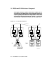
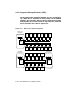
Each of the two DSSI buses per KFMSA has eight data lines: 1 parity
line and 7 control lines. Transmission on the DSSI bus is packet-oriented.
Of the eight nodes configured between any two terminators on KFMSA
adapters, one to three nodes can be KFMSA adapters. The remaining
nodes can be RF disk or TF tape integrated storage elements (ISEs). See
Section 3.4.2.
The level 3 diagnostic, EVCXF, reports ISE node IDs and connection on
each bus (described in Section 3.6.3).
FOR MORE INFORMATION
Primary reference: KFMSA Module Installation and User Manual
Secondary reference: KFMSA Module Service Guide
Connecting to a DSSI Subsystem 3–11