
Installation guide
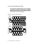
On both CI and DSSI, all nodes directly connect to each other. The DSSI
bus requires electrical terminators at both ends to ensure signal integrity
because it is DC-coupled (the CI bus does not require physical termination).
Logically, each DSSI bus is equivalent to a small CI with its Star Coupler.
The RF/TF devices on the DSSI are functionally equivalent to a combination
of HSC and RA/TA devices on the CI. Like the HSC, each ISE controller
can communicate with multiple VAX hosts on DSSI and order disk seeks.
ISEs do not have to share an HSC like CI devices, so each additional ISE
linearly increases I/O throughput and bandwidth.
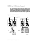
DSSI can be implemented in single-, dual-, or tri-host mode. In single-
host, one system has access to integrated storage elements (ISEs) across
the DSSI storage bus. In dual- and tri-host configurations, the systems
remain functionally independent while their common DSSI storage bus,
together with VAXcluster software, makes the ISEs available to each
system, providing multiple data paths for access to the ISEs.
Dual- and multi-host systems can include multiple VAX 6000 systems and
VAX 4000 Model 300 systems (see Section 3.4.6).
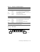
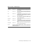
FOR MORE INFORMATION
Primary reference: KFMSA Module Installation and User Manual
Secondary reference: SF2xx Storage Array Installation Guide
Connecting to a DSSI Subsystem 3–7