
Installation guide


Typically, the DWMBB/A modules for an expansion cabinet are installed in
slots 1 through 3 of the XMI card cage (although they can be placed in any
slot except slots 6 through 9).
Two 15-foot cable assemblies (17-01897-01) are used to connect the DWMBB
modules. Each cable assembly consists of two ribbon cables bundled
together. See Section C.5 for DWMBB/A slot allocation in the XMI card
cage. The cables connect to the expander card cage backplane at slot 1.
CAUTION: You must wear the antistatic wrist strap attached to the
cabinet when you handle any modules.
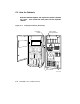
1. Remove the clear plastic door in front of the XMI card cage and install
the DWMBB/A module in slot 1. Replace the door.
2. Check to see that the AC OK/DC OK cable, 17-01920-01, is installed in
the VAXBI backplane at slot 1, segment C1.
3. Lay the four cables out flat. Mark each end, as shown in Table C–1.
NOTE: Install the cable so that the red stripe on each cable is up, away
from the bottom of the card cage.
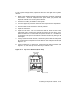
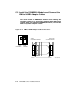
4. At slot 1 of the expander cabinet backplane, connect the cables as
you have marked them. Insert cables 1 and 2 into segments D2 and
D1; insert cables 3 and 4 into segments E2 and E1, respectively (see
Figure C–4).
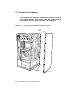
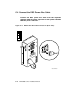
5. Route the cables through the wave guide slot and into the system
cabinet (see Figure C–3).
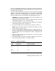
6. At the XMI backplane, connect the cables to segments D and E as you
have marked them (see Table C–1 and step 3 above).
Table C–1: Cable Connections
Cable
From VAXBI Expander
Connection To XMI Connection
Cable 1 D1 D2
Cable 2 D2 D1
Cable 3 E1 E2
Cable 4 E2 E1
Installing an Expander Cabinet C–7