
Installation guide
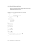


Set the lower key switch to Update.
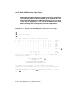
Enter the console command SHOW CONFIGURATION.
In this example the DWMBB/A adapter is XMI node E. The self-test
display shows the VAXBI devices attached through node E.
The VAXcluster controller (CIBCA) is shown in the second column. The
CIBCA device type is 0108. In this example the controller is VAXBI
node 2, shown in the first column.
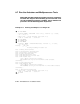
Qualifier /XMI specifies XMI node E.
Qualifier /BI specifies VAXBI node 2.
Qualifier /NODE specifies the CI node number of the HSC controller.
In this example the system disk is dual-ported to two HSC controllers
at nodes 04 and 05. A disk ported to only one HSC has a qualifier
like /NODE:04. See Chapter 4, Connecting to a CI VAXcluster, for
instructions on setting VAXcluster nodes and numbers.
Qualifier /R5 is used to load register R5 with the number of the root
directory for the operating system. In this example the root is SYS4.
Note that the root directory number must be in the high-order four bits.
In this example the system disk is unit number 0 on the HSC controller.
You can now boot from the VAXcluster path by issuing the BOOT
command.
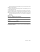
The second SET command defines a path for booting from a local disk
instead of from the VAXcluster. The boot name LOC is arbitrary. The
path is disk unit number 1 on the disk controller whose VAXBI node
number is 4. (Refer to the SHOW CONFIGURATION display; the
KDB50 is node 4 of the VAXBI. The DWMBB/A adapter is node E on
the XMI bus.)
You can now boot from the local disk by issuing the BOOT LOC
command.
When you are finished setting EEPROM parameters, turn the lower key
switch to Halt or Auto Start.
Verification 8–23