
Installation guide
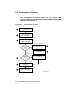

When the VAX 6000 powers up, self-test runs. The self-test for Models
500 and 600 includes a multiprocessor test. For Models 300 and 400,
self-test does not include the multiprocessor test; it must be run in a
separate step.
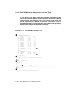
Issue the SHOW CONFIGURATION command. For CD server booting,
locate the Ethernet or FDDI adapter node address. For tape booting,
locate the tape adapter node address. See Section 8.3.
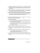
Check the console load device hardware. Check the Ethernet adapter by
examining the self-test results and the green test light on the module,
which reports the results of Ethernet loopback tests (see Section 8.4.1).
For tape, run ROM-based diagnostics (see Section 8.4.2).
If you are installing a Model 500 or 600, go to step . If you are installing
a Model 300 or 400, do steps and .
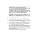
For Models 300 and 400:
For CD server booting, load and boot the VAX 6000 diagnostic CD-
ROM, part number AG–PDWW*–RE, labeled VAX 6000 CMPLT
DIAG CD-ROM (see Section 8.6.1).
For booting from tape, load and boot the VAX 6000 diagnostic tape,
part number AQ–PDWX*–DE, labeled VAX 6000 CMPLT DIAG
TK50 (see Section 8.6.3).
Run VAX/DS, the autosizer, and multiprocessor tests.
If the system has a KFMSA adapter, go to Section 3.4.1 and follow the
directions to run EVCXF under VAX/DS at this point in the verification
procedure.
Set and store system parameters.
1
Record system parameters using:
For Models 500 and 600: SHOW ALL and SHOW FIELD
For Models 300 and 400: SHOW ALL
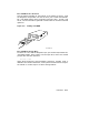
For TK systems only (not for TF tape): SAVE EEPROM
Load and boot the operating systemCD-ROM.Refer to operating system
installation manuals. Verify the system under the installed operating
system.
1
Store printout in the maintenance envelope on the back door of the cabinet and in your
Site Management Guide.
Verification 8–5