
Installation guide
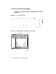


The first line shown in Example 7–1 is the progress trace line and, if
complete, shows that the CPU in slot 1 passed all testing. If the final
# sign is missing, the last number shown is the number of the failing
test. This line of numbers is displayed only by the processor in slot 1,
and only when this processor undergoes power-up or a system reset.
This processor is not always the boot processor.
For example, when the system is reset or the INITIALIZE command is
issued, the progress trace line might show:
#123456789 01234567 ! Test #17 (decimal) failed.
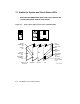
The NODE # line lists the node numbers on the XMI bus. The nodes
on this line are numbered in hexadecimal and reflect the position of the
XMI slots as you view the XMI from the front of the cabinet.
The TYP line in the printout indicates the type of module at each XMI
node:
An I/O adapter (A)
A scalar processor (P)
A vector processor (V, on Models 400 and 500 only)
A memory module (M)
A period indicates that the slot is not populated or that the module
is not reporting and may be dead.
The STF line shows the results of self-test. This information is taken
from the self-test fail bit in the XBER register of each module. The
entries are:
+ (pass)
– (fail)
o (device is not tested at this step in the sequence)
You can enter HELP SELFTEST_OUTPUT at the console prompt for more
information on the self-test display lines. Or refer to the VAX 6000 Series
Owner’s Manual.
System Self-Test 7–5