
Installation guide
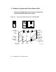


1. Turn the upper key switch to Enable. The following should occur:
a. The red Fault indicator lights on the control panel. This indicator
should turn off within 60 seconds.
b. The green lights on the five power regulators go on. The lights are
visible from the rear of the cabinet.
c. The blowers turn on.
d. The module LEDs go on.
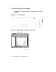
e. The console terminal prints the results of self-test for the XMI.
The results printed should be similar to Example 7–1. If an
optional VAXBI is installed, the printed results should be similar
to Example 7–2.
2. Table 7–1 lists each module’s LED status indicating self-test passed or
self-test failed.
Table 7–1: LEDs After Self-Test
Module Self-Test Passed Self-Test Failed
Boot processor Yellow ON, top two red ON
for Models 500 and 600;
only top red ON
for all other models
Yellow OFF
Some red ON
1
Vector processor(s)
2
Yellow ON Yellow OFF
Secondary processor(s) Yellow ON, top two and bottom red ON
for Models 500 and 600;
top and bottom red ON
for all other models
Yellow OFF
Some red ON
Memory Yellow ON
Green ON
Yellow ON
3
Green ON
VAXBI adapter Yellow ON Yellow OFF
1
CPU modules have seven or eight red LEDs. This group of LEDs is used to dis-
play the number of the test that failed. On the Model 500 module, an addi-
tional red LED, the error summary, lights if any test failure results in any hard-
ware error bits being set. Refer to your system’s service manual for more informa-
tion.
2
Vectors available on Models 400 and 500 only.
3
The yellow indicator on the memory module is used to indicate only that self-test has com-
pleted.
System Self-Test 7–3