
Installation guide
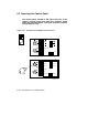
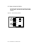
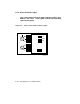
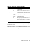


Table 6–2: Upper Key Switch
Position Effect Light Color
O (Off) Removes all power, except to the battery backup unit and
optional storage.
No light
Standby Supplies power to XMI backplane, blowers, and in-
cabinet console load device.
Red
Enable Supplies power to whole system; console terminal is en-
abled. Used for console mode or restart, and to start self-
test.
Yellow
Secure
(Normal Posi-
tion)
Prevents entry to console mode; position used while ma-
chine is executing programs. Disables Restart but-
ton and causes the lower key switch to have the ef-
fect of Auto Start, regardless of its setting.
Green
Table 6–3: Lower Key Switch
Position Effect Light Color
Update Enables writing to CPUs and adapters. Halts boot pro-
cessor in console mode on power-up or when Restart
button is pressed. Used for updating parameters stored
in EEPROMs, (upper key switch must be set to En-
able). Prevents an auto restart.
Red
Halt Prevents an auto restart if a failure or tran-
sient power outage occurs.
Yellow
Auto Start
(Normal Position)
Allows restart or reboot. Uses the default boot specifi-
cation to boot the system from power-up. Used for nor-
mal operation of the system.
Green
Powering Up the System 6–13