
Installation guide

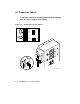
WARNING: To avoid high voltage shock, a round, threaded cap is provided
to cover the unused power input connector. When replacing, rewiring, or
reconnecting the transformer, make sure that the cap is properly installed.
The cap fits onto either the 380V AC (J2) or the 416V AC (J1) power input
connector. Always ensure that power is off and that the power cable is
unplugged before working on the transformer.
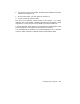
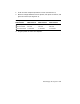
1. Open the cabinet front door. Transformer cable connections can be
viewed through the open space between the H7206-B power and logic
unit and the sheet metal panel below the H7206-B.
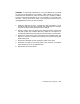
2. Visually check to see if the power input cable connection matches the
customer’s power source (either 380V AC or 416V AC). See Figure 6–2.
Complete procedure steps3 through 6 if the cable requires reconnection.
3. Remove the sheet metal panel located below the H7206-B power and
logic unit. Use a flat screwdriver to remove the six screws securing the
sheet metal panel.
4. Remove the threaded cap and unplug the power input cable.
5. Reconnect the cable to the correct power input connector and replace
the threaded cap on the unused connector.
6. Replace the sheet metal panel.
Powering Up the System 6–5