
Installation guide
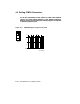

1. Open the rear cabinet door.
2. Find the VAXBI backplane slot corresponding to the CIBCA controller
module (T1045). The two CIBCA modules occupy adjacent slots;
the controller module is the leftmost module as seen from the rear.
(Typically the controller is in the VAXBI cage on the left, fourth slot
from the left as seen from the rear.)
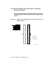
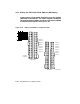
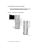
3. Insert jumpers between backplane pins to set the cluster node address,
as follows. You set the address twice—once on VAXBI segment D and
once on segment E (see Figure 4–9).
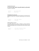
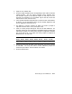
4. The address is a binary number, for which you insert a jumper to
represent each bit that is "one" (see Figure 4–10).
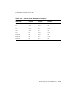
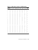
5. Table 4–7 shows jumper settings for the first 24 node addresses. For
example, assumeyou are installing this VAX 6000 system as VAXcluster
node 9 (binary 1001). You would insert jumpers on segment D between
pins 9–39 and 12–42. You would also insert jumpers on segment E
between pins 5–35 and 8–38.
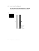
D5–35
E1–31
D6–36
E2–32
D7–37
E3–33
D8–38
E4–34
D9–39
E5–35
D10–40
E6–36
D11–41
E7–37
D12–42
E8–38
OUT OUT OUT OUT IN OUT OUT IN
6. If there are more than 16 nodes in the VAXcluster, also insert a jumper
in D30–D60. You may also need to install additional jumpers for
VAXcluster parameters. See the CIBCA User Guide.
7. Close the cabinet door.
Connecting to a CI VAXcluster 4–21