
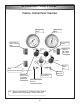
Specifications

m WARNING: Prior to performing any type of main-
tenance work on your ProVax, insure that it is dis-
connected from the power supply before you begin.
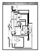
NOTE: Refer to the wiring diagram on page 17 dur-
ing the installation of your kit.
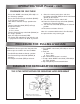
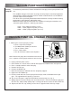
1. Disconnect your ProVax from the power source.
2. Remove the case fasteners and separate the front
half of the ProVax.
3. Identify white "jumper wire," located below hole in
lower right corner of the front panel, designated
for the tank sensor cord.
Note: Jumper wire identified with a tag.
4. Disconnect jumper where tagged and secure it to
nearest wire bundle, using wire tie provided.
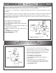
5. Route tank sensor cord (EL1420) through the hole
in the front panel, passing the "tank connector"
end through from the backside.
6. Secure the tank sensor cord in the hole with the
strain relief grommet provided.
7. Connect the 3-pin male connector (white) supplied
with the KT5002 to its counterpart, pre-wired
inside your ProVax.
8. Secure any loose wiring with the wire ties
provided.
9. Replace the plastic case halves and fasteners.
10. To test the installation:
a. Attempt to start the ProVax without the sensor
cord attached to a tank. The ProVax’s
compressor should not start up.
b. Turn the ProVax off and attempt to start the
ProVax with the sensor tank connected to a
tank. The unit should function normally.
Disconnecting the sensor cord while the unit
is running should cause the unit to shut down.
11 If your unit does not function as described
above, DISCONNECT the ProVax from the
power supply, and re-check your connections
per the steps above and the wiring diagram on
page 17.
INSTALLATION OF OPTIONAL 80% TANK SHUT-OFF KIT
CAPACITY SENSING COMPONENTS (P/N:KT-5002)
19