
Specifications


3-18 888-2857-001 5/9/13
WARNING: Disconnect primary power prior to servicing.
Section 3 Operation
Platinum VAX-C Series
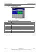
Main/Standby This field indicates the on-air status. In a dual drive system, an active
transmitter will display Main (green field). The inactive exciter will display
Standby (in blue).
Mute/MUTE This field indicates the mute status of the exciter section. If RF output is
muted, this field displays MUTE (uppercase, red field). If the output is not
muted, the field displays Mute (lowercase, green field). When the transmitter
is switched OFF, the MUTE field will be red.
OK/WARNING/
FAULT
This field indicates a summary status of the exciter section. If no warnings or
faults exist within the exciter section, the indication displays OK (green
field). When an exciter parameter approaches its limit, the fields displays
WARNING (yellow field). If a fault occurs within the exciter, the field
displays FAULT (red field).
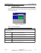
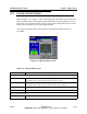
RTAC Window The RTAC (Real Time Adaptive Correction) section of the Exciter Home Screen displays the
operating mode of the correctors. The RTAC section of the Exciter Home screen is a soft key. When selected by
left mouse click, the first screen of RTAC Setup is presented.
Linear Corrector uses RF feedback sample taken after the high power filter. Used to
correct for filter distortions in amplitude and group delay. See Figure 2-5 on
page 2-17.
Nonlinear Corrector uses RF feedback sample taken before the high power filter. Used to
correct for linearity and incidental phase distortion in the high power
amplification stages.
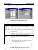
Linear and Nonlinear
Modes
Adapt: The correction algorithm is active and will continuously calculate and
update correction as needed.
Hold: The RTAC circuit keeps the last correction value for the selected
mode. This is a short term option. For long term use select Stored.
Stored: The RTAC circuit preloads a stored correction algorithm from one of
the stored Correction Sets. This represents a long term storage method.
Bypass: Turns the selected corrector off.
System Output Sub Window
Graph Displays the spectrum response of the signal that is connected to the
transmitter post filter input on the back of the unit. See Figure 2-5 on page 2-
17 for connection location.
Softkeys
Xmtr Home Displays the Xmtr Home screen.
Setup Pressing this soft key displays the Main ’Setup’ Screen in Figure 3-14 on page
3-21. This screen accesses the various setup screens for the transmitter. See
Section "3.4 SETUP SCREENS, All Modulation Systems" on page 3-21.
Status Pressing this soft key displays the Main ’Status’ Screen in Figure 3-51 on
page 3-81. This screen accesses the various Status screens for the transmitter.
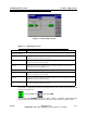
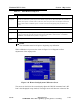
Table 3-9 Exciter Home Screen
Window Description