
Specifications


vi 888-2857-001 5/9/13
WARNING: Disconnect primary power prior to servicing.
Guide to Using Parts List Information
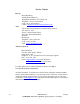
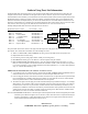
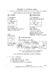
The Replaceable Parts List Index portrays a tree structure with the major items being left most in the index. The
example below shows the Transmitter as the highest item in the tree structure. If you were to look at the bill of
materials table for the Transmitter you would find the Control Cabinet, the PA Cabinet, and the Output Cabinet. In the
Replaceable Parts List Index the Control Cabinet, PA Cabinet, and Output Cabinet show up one indentation level
below the Transmitter and implies that they are used in the Transmitter. The Controller Board is indented one level
below the Control Cabinet so it will show up in the bill of material for the Control Cabinet. The tree structure of this
same index is shown to the right of the table and shows indentation level versus tree structure level.
Example of Replaceable Parts List Index and equivalent tree structure:
Replaceable Parts List Index Part Number Page
Table 7-1. Transmitter 994 9283 001 7-2
Table 7-2. Control Cabinet 992 9244 002 7-3
Table 7-3. Controller Board 992 8344 002 7-6
Table 7-4. PA Cabinet 992 9400 002 7-7
Table 7-5. PA Amplifier 994 7894 002 7-9
Table 7-6. PA Amplifier Board 992 7904 002 7-10
Table 7-7. Output Cabinet 992 9450 001 7-12
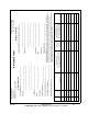
The part number of the item is shown to the right of the description as is the page in the manual where the bill for that
part number starts. Inside the actual tables, four main headings are used:
• Table #-#. ITEM NAME - PART NUMBER - this line gives the information that corresponds to the
• Replaceable Parts List Index entry;
• P/N column gives the ten digit part number (usually in ascending order);
• DESCRIPTION column gives a 25 character or less description of the part number;
• REF. SYMBOLS/EXPLANATIONS column 1) gives the reference designators for the item (i.e., C001,
R102, etc.) that corresponds to the number found in the schematics (C001 in a bill of material is equivalent
to C1 on the schematic) or 2) gives added information or further explanation (i.e., “Used for 208V operation
only,” or “Used for HT 10LS only,” etc.).
NOTE: Inside the individual tables some standard conventions are used:
• A # symbol in front of a component such as #C001 under the REF. SYMBOLS/EXPLANATIONS column
means that this item is used on or with C001 and is not the actual part number for C001.
• In the ten digit part numbers, if the last three numbers are 000, the item is a part that has been purchased and
has not manufactured or modified. If the last three numbers are other than 000, the item is either manufac-
tured or is purchased from a vendor and modified for use in the product.
• The first three digits of the ten digit part number tell which family the part number belongs to - for example,
all electrolytic (can) capacitors will be in the same family (524 xxxx 000). If an electrolytic (can) capacitor
is found to have a 9xx xxxx xxx part number (a number outside of the normal family of numbers), it has
probably been modified in some manner at the factory and will therefore show up farther down into the indi-
vidual parts list (because each table is normally sorted in ascending order). Most made or modified assem-
blies will have 9xx xxxx xxx numbers associated with them.
The term “SEE HIGHER LEVEL BILL” in the description column implies that the reference designated part number
will show up in a bill that is higher in the tree structure. This is often the case for components that may be
frequency determinant or voltage determinant and are called out in a higher level bill structure that is
more customer dependent than the bill at a lower level.
Transmitter
994 9283 001
Control Cabinet
992 9244 002
Controller Board
992 8344 002
PA Cabinet
992 9400 002
PA Amplifier
992 7894 002
PA Amplifier Board
992 7904 002
Output Cabinet
992 9450 001