
Specifications


2-16 888-2857-001 5/9/13
WARNING: Disconnect primary power prior to servicing.
Section 2 Installation / Initial Turn-On
Platinum VAX-C Series
2.10 RF Connections
2.10.1 RF Output
Prior to operation the transmitter RF output connector must be connected to a known
good test load or antenna with a high quality 50 ohm RF cable. A patch panel may also
be used if switching between load and antenna is desired.
A type N male connector is needed for the transmitter output side of the cable. The
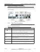
VAX-C output connection is located on the rear panel see Section Figure 2-5 on page 2-
17. The connector needed for the load, filter or antenna end of the cable may vary
depending on the customer’s system. Initial testing into a 50 ohm test load is
recommended. VSWR (voltage standing wave ratio) of the test load should be <1.05:1,
antenna system <1.2:1, and filter <1.1:1. The VAX-C will operate into a VSWR of 1.5:1
maximum but a lower system VSWR is recommended for reliable operation.
2.10.2 RF Sample Connections and Level
An RTAC post-filter RF feedback signal is required for RTAC to perform linear
precorrection. If the unit is running in RTAC stored mode then this post-filter sample is
not required.. The RF sample input connector is located on the VAX-C rear panel and
shown in Figure 2-5. The feedback sample is taken from the directional coupler located
after the system mask filter. If no mask filter is used or required then the feedback
should be via a coupler at the output of the system. The coupler can be ordered from
Harris as an option. If the transmitter system is a 1+1 (main/standby) configuration,
feedback samples for each transmitter are obtained by splitting the post filter sample
cable.
With the transmitter operating at full TPO the post-filter RTAC sample signals at the
VAX-C input should be padded to yield a nominal 0 to -5 dBm at the highest expected
transmitter output power. The post filter sample input power range is -20 to +5 dBm.