
Specifications


5/9/13 888-2857-001 2-13
WARNING: Disconnect primary power prior to servicing.
Section 2 Installation / Initial Turn-On
Platinum VAX-C Series
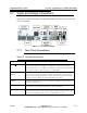
2.7.3 Transmitter Interface Connector
The 25 pin, male, connector is labeled Transmitter Interface and located on the VAX-C
rear panel. It can be used for remote control and monitoring on standalone transmitters.
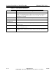
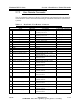
Table 2-4 Rear Panel, ’Tx Interface’ Connector
LPU TX Interface Connector -25 Pin Male
Signal Direction Description, Control I/O Assignment
1
/Power Raise Input Power Raise Command I/O Bus 0
2
/Power Lower Input Power Lower Command I/O Bus 1
3
TX On Input
Transmitter On Command
I/O Bus 2
4
/TX Off Input
Transmitter Off Command
I/O Bus 3
5
Not Used Input
I/O Bus 4
6
/RF Mute Command
Input
RF Mute Command
Indirectly to Signal Pro-
cessing board
7
/Sum Fault
Output
Summary Fault Status
I/O Bus 5
8
/RF Mute Status
Output
RF Mute Status
I/O Bus 6
9
/UPS Shutdown
Input
Disables battery backup functionality
Indirectly to Signal Pro-
cessing board
10
/EQ Reset
Input
Resets adaptive correction tables to
default
I/O Bus 16
11
EQ/Hold
Input
Holds current adaptive correction
tables
I/O Bus 7
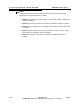
12
Not Used
Input Analog Input 0
13
Not Used
Input Analog Input 1
14
Not Used
Input I/O Bus 8
15
/RF Present
Output
Indicates that the exciter RF output is
valid
I/O Bus 9
16
On/Off Status
Output
Transmitter On/Off Status
I/O Bus 10
17
/Remote Fault Reset
Input
Restrike Command
I/O Bus 11
18
Not Used
Input I/O Bus 12
19
Not Used
Input I/O Bus 13
20
Exciter/LPU Sum Flt
Output
Exciter LPU Summary Fault Status
I/O Bus 14
21
Remote Enable/Disable
Output
Remote Control Status
I/O Bus 15
22
GND Ground
23
GND Ground
24
GND Ground
25
GND Ground