
Specifications


5/9/13 888-2857-001 2-11
WARNING: Disconnect primary power prior to servicing.
Section 2 Installation / Initial Turn-On
Platinum VAX-C Series
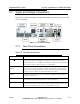
2.7.2 User Remote Connector
This 25 pin female connector is labeled ’User Remote’ and located on the rear panel. It
can be used for remote control and monitoring on standalone transmitters (non-racked
systems).
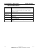
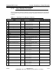
Table 2-3 Rear Panel, ’User Remote’ Connector
User Remote - 25 Pin Female
Signal Direction Description Control I/O Assignment
1
Forward Power Output 0 – 4.096VDC output representing
Forward power level
Analog Output 0
2
Reflected Power Output 0 – 4.096VDC output representing
reflected power level
Analog Output 1
3
Spare Analog In 1 Input Analog Input 2
4
Spare Analog In 2 Input Analog Input 3
5
+12Vdc Output
+12Vdc, 200mA max
6
GND Ground
7
GND Ground
8
GND Ground
9
GND Ground
10
GND Ground
11
Alarm O Common Alarm 0 Relay Common
12
Alarm 0 Normally Closed
Alarm 0 Relay Normally Closed
(Faulted) Position
13
Alarm 0 Normally Open
Alarm 0 Relay Normally Open (Non-
Faulted) Position
14
Alarm 1 Common Alarm 1 Relay Common
15
Alarm 1 Normally Closed Alarm 1 Relay Normally Closed
(Faulted) Position
16
Alarm 1 Normally Open
Alarm 1 Relay Normally Open (Non-
Faulted) Position
17
Alarm 2 Common
Alarm 2 Relay Common
18
Alarm 2 Normally Closed Alarm 2 Relay Normally Closed
(Faulted) Position
19
Alarm 2 Normally Open Alarm 2 Relay Normally Open (Non-
Faulted) Position
20
Alarm 3 Common Alarm 3 Relay Common
21
Alarm 3 Normally Closed Alarm 3 Relay Normally Closed
(Faulted) Position
22
Alarm 3 Normally Open Alarm 3 Relay Normally Open (Non-
Faulted) Position
23
Alarm 4 Common Alarm 4 Relay Common
24
Alarm 4 Normally Closed Alarm 4 Relay Normally Closed
(Faulted) Position
25
Alarm 4 Normally Open Alarm 4 Relay Normally Open (Non-
Faulted) Position