
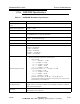
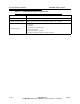
Specifications


5/9/13 888-2857-001 2-3
WARNING: Disconnect primary power prior to servicing.
Section 2 Installation / Initial Turn-On
Platinum VAX-C Series
2.5 Installation
NOTE:
This equipment is intended only for installation in a RESTRICTED ACCESS
LOCATION.
Steps in the installation section are numbered in each section. As each step is
completed, the step number can be circled to indicate completion. This provides a quick
confidence check at the end of the procedure that no steps were skipped.
NOTE:
In case of discrepancy between the connections listed in diagrams versus infor-
mation given in this installation section, the wiring information in the diagrams
should be considered the most accurate. All connections listed in this section
should be verified with the schematics before initial turn on.
When performing the installation, after the transmitter is in place, plan to run the
transmitter output transmission lines first, then the air cooling system components (if
ducting is used), and finally the electrical conduit runs.
NOTE:
If air handling duct work is to be installed, plan all of the RF and conduit runs to
leave room for the duct work.
The reason for this installation order is that rigid coax runs need to be installed using
minimum elbows. Installation of RF lines is more complicated if obstacles like conduit,
and ductwork are in place. The RF lines should have a minimum number of elbows for
best performance.
NOTE:
RF coaxial lines must be properly supported.
2.5.1 Transmitter Placement and Operating Environment
The selection of a proper installation location is essential for equipment longevity and
reliability. Do not install the transmitter in places where it may be exposed to
mechanical shocks, excessive vibration, dust, water, or acidic gas.
Ambient temperature and relative humidity should always range between the following
limits at the installation location:
• Ambient temperature: 0 to +45
o
C. (0 to +40
o
C. for UL 60950)
• Relative humidity: 0 to 90% non-condensing