
Specifications


1-12 888-2857-001 5/9/13
WARNING: Disconnect primary power prior to servicing.
Section 1 Introduction
Platinum VAX-C Series
depending on the modulation standard. See section 3 for modulation dependent input
connector configurations. The modulation process is fully digital, with analog circuits
used after the D/A converter to up-convert the IF signal to the desired channel.
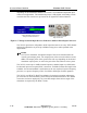
Figure 1-5 Transport Stream Input Presence Indicators and Rear Panel Input Connectors
The VAX-C upconverter will produce an RF output that can be set to any VHF channel
and may be adjusted to any level up to 6dBm average power when operated in the
digital mode.
NOTE:
In a VAX-C transmitter, the adjusted output of the exciter will determine the
overall system output power. The output power of the exciter should not exceed
6dBm. The output power of the upconverter will vary depending on the desired
transmitter output power, as well as the gain of the PA(s) that are in the system.
The VAX-C can accept a 10 MHz external frequency standard input or a 1PPS (Pulse
Per Second) input via rear-panel, BNC, connectors. An SMA (female) GPS input is also
available. An external standard is used whenever the user requires increased frequency
precision, or a precise frequency offset. Use 1PPS or GPS input for SFN operation.
The VAX-C uses RTAC™ (Real Time Adaptive Correction) to monitor and manage
pre-correction for the transmitter system’s linear and nonlinear distortion. No manual
correction circuits are employed. Low power RF samples from various stages of the
transmitter are required by the RTAC circuits.
ATSC Modulator Status Screen
Transport Stream Indicators
Rear Panel Transport Stream
Input Connectors