
Specifications


5/9/13 888-2857-001 1-11
WARNING: Disconnect primary power prior to servicing.
Section 1 Introduction
Platinum VAX-C Series
1.9 VAX-C Exciter/Controller
The VAX-C exciter section is a transmitter RF signal source. It receives the program
material to be transmitted in the form of a digital transport stream and generates a low-
level on-channel RF signal. It performs pre-corrections for non-linear distortions which
occur in the transmitter RF power amplifier and for linear distortions/group delay which
occur in the high power filter.
The VAX-C can be operated with multiple digital modulation platforms by changing the
software and updating the feature key (feature key updates may not be required, it
depends on how the system was initially purchased).
The heart of the VAX control system is a microprocessor daughter board located on the
signal processing board in the VAX-C chassis. The front of the VAX-C includes a
control panel and LCD screen. There are two RJ45 ethernet connectors. One ethernet
connector is located on the front control panel. This connector has a static IP address
and acts as a DHCP server. The other RJ45 ethernet connector is on the rear of the unit
and can be configured as a DHCP client or assigned a static network IP.
The VAX-C contains two muffin fans mounted in the right and left sides of the chassis
front. Cooling air is drawn into the assemblies from the front and forced over the top
and bottom sides of the circuit boards, and exits from the rear of the VAX-C exciter
section. The left fan cools the exciter part of the unit and the right fan cools the PA
section. The fans are not redundant.
The VAX-C top cover may be removed to provide access to the circuit boards, power
should be disconnected before the top cover is removed. See Figure 1-2 on page 1-3 for
the names and locations of the various circuit boards in the VAX-C.
All system interconnections are via the rear panel, see Figure 1-3 on page 1-4.
A vertical column of seven LEDs on the front panel provide status for TS Input, Drive
Chain, Power Amp, Power Supply, Output, System and Mute. Refer to Section 3.1.3 on
page 3-6 for descriptions of the front panel LEDs.
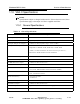
1.9.1 Inputs and Outputs
The RF output can be set to any VHF channel and the output power is maintained via
automatic level control (ALC).
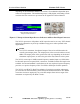
The VAX-C has four digital input program streams via the rear panel BNC input
connectors, shown in Figure 1-5. Most modulation standards only use two of them at a
time as a main and alternate inputs. The program inputs may be ASI or SMPTE310