
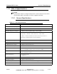
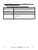
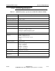
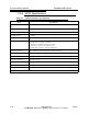
Specifications


5/9/13 888-2857-001 1-7
WARNING: Disconnect primary power prior to servicing.
Section 1 Introduction
Platinum VAX-C Series
1.5 VAX Transmitter System
VAX-C transmitters feature solid-state design and utilize a FET-based power amplifier
(PA) module to amplify the RF signal. In addition to RF drive power from the exciter
stage, the PA module utilizes 50V DC power, supplied by a switch mode power supply
(PS) module.
The PA module type varies with power level. The VAX-C features two cooling fans that
can be changed by removing the front panel while the transmitter is on-air. Transmitters
are typically supplied without a rack. Rack mounting is available as an option.
The VAX-C system control is provided by the microprocessor daughter board which is
mounted on the signal processing board, as shown in Figure 1-2 on page 1-3. SNMP
communications and IP connectivity are standard offerings and available in all
transmitter models. The VAX-C transmitter has an LCD display and control buttons on
the front panel to allow the user to locally control the transmitter as shown in Figure 1-
1 on page 1-3. LCD panel and push button control provides limited control of the
transmitter system. The feature key and modulation settings can’t be changed using the
LCD control panel push buttons. The web browser must be used to change these
parameters.
1.5.1 Transmitter RF Power Control
The PA module itself operates in open loop mode (no gain or level adjustment). The
transmitter RF power control is done via automatic level control located in the VAX-C
upconverter.
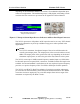
1.5.2 Software
The transmitter is shipped from the factory with software preloaded and ready to run. If
a software update is required, follow the instructions in the maintenance and alignment
section. Software can be easily updated using the web browser and ISP (In System
Programming). ISP is a Harris programming utility that is selectable as part of the web
browser interface. See 3.4.1 for further details.
1.5.3 Remote Control
The Platinum VAX-C transmitter has a wired parallel remote control with the standard
connections for control, status and analog monitoring located on the customer I/O card
in the rear panel. Detailed information on the remote control connections to the VAX-C
and cabinet can be found in Section 2.7.