
Specifications


6-4 888-2857-001 5/9/13
WARNING: Disconnect primary power prior to servicing.
Section 6 Diagnostics
Platinum VAX-C Series
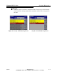
6.3 Fault Tables
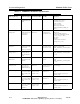
The following tables provide a listing of VAX-C Transmitter faults along with a brief
description, the fault level or threshold and the action taken by the transmitter.
Table 6-1 UDC Faults
Fault Log
Message
Fault Description Front Panel LEDs
Nominal Value/
Scaling
Trip Level
Upconverter IF
level
Indicates up/down converter
IF level is out of range low
Mute LED red.
System and Mute
LEDs red.
1000mV +/-
100mV, detector
referenced to mixer
input level.
900mV NOTE: Test tone levels have
not been characterized for any special
considerations. Indicated levels are for
normal modulation.
Upconverter IF
level
Indicates up/down converter
LO level is out of range high
System and Mute
LEDs red.
1000mV +/-
100mV, detector
referenced to mixer
input level.
> 1100mV NOTE: Test Tone levels
have not been characterized for any
special considerations. Indicated
levels are for normal modulation.
Upconvertor
LO level
Indicates up/down converter
LO level is out of range low
System and Mute
LEDs red.
0dBm LO level < -5.6dBm
Upconvertor
LO level high
U converter LO level high
warning
System LED
orange.
LO Level Input
should be 0dBm
LO level > -5.4dBm
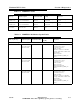
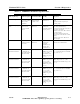
Table 6-2 MODFPGA Faults
Fault Log
Message
Fault Description Front Panel LEDs
Nominal Value/
Scaling
Trip Level
Modulator Not
Alive
Indicates MOD FPGA is in
known good state
System and Mute
LEDs red.
Data pattern written/
read over HPI matches
Data pattern written/read
over HPI does not match
Modulator
Temperature
Fault
Indicates MOD FPGA is
over temperature
System and Mute
LEDs red.
Over temperature less
than 4 times. 85 C
limit.
Over temperature 4 times
(no time limit). 85 C limit
Modulator DAC
Clock
Indicates DAC clock is
present in MOD FPGA
System and Mute
LEDs red.
DAC clock detected DAC clock is not detected
Modulator
Sample Clock
Indicates MOD clock is
present in MOD FPGA
System and Mute
LEDs red.
Modulator sample
clock and 10 MHz
internal clock edges are
both detected
Either modulator sample
clock or 10 MHz internal
clock edges are not detected
Modulator 4X
Sample Clock
Indicates MOD clock x4 is
present in MOD FPGA
System and Mute
LEDs red.
Modulator 4 x sample
clock edges are
detected
Modulator 4 x sample clock
edges are not detected