
Specifications


5/9/13 888-2857-001 6-1
WARNING: Disconnect primary power prior to servicing.
Platinum VAX-C Series
Section 6
Diagnostics
6
6.1 Introduction
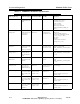
This section contains diagnostic and troubleshooting information for the VAX-C series
VHF transmitter. Included is a complete description of all faults which can be displayed
via the transmitter front panel LCD, Web Interface or TCU (transmitter control unit
GUI (Graphical User Interface). Due to the complexity of the transmitter control system
and the extensive use of surface mount components, the scope of this diagnostics
section is to isolate the problems down to a PC board or module level which can then be
easily exchanged.
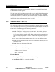
The buttons and icons used in the web browser use a color code system. Some examples
are given below.
a. Green with a 1 - - ON and operating normally.
b. Green symbol - - ON and operating normally.
c. Light Gray - - "Grayed Out" - Not communicating or not available.
d. Yellow - Warning - A non-critical sub-
system or parameter is out of tolerance and should be addressed by engineering
personnel.
e. Red - - Critical Fault - This could be a sub-system fault in which the sub-
system is muted or shut off (such as a PA module) or could be a system level fault
which could mute or shut the transmitter off.
When a fault occurs, one or more of the LED’s on the transmitter control panel will
illuminate red. To track down the cause of the fault, open the transmitter fault log via