
Specifications


5-12 888-2857-001 5/9/13
WARNING: Disconnect primary power prior to servicing.
Section 5 Maintenance and Alignments
Platinum VAX-C Series
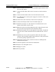
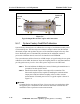
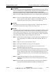
Figure 5-6
Typical Output Directional Coupler and Connections
5.4.1 System Factory Fwd/Rfld Calibration
System factory forward power is calibrated over a range of 10 dB below model power
to full model power. The forward power reference sample is taken from the internal
directional coupler and regulates the power of the transmitter output before any filter
losses. Reflected power is automatically calculated as the calibration routine is
processed. Calibration data is stored on a PA interface board EEPROM.
The system detectors utilize a linear (in mV/dB) output, so by performing the two-point
calibration at 205 MHz, the detector slope and coupling factors are calculated and thus
provide good accuracy over the 10%-100% power range across the VHF band.
STEP 1 Zero and calibrate the RMS power meter, following the manufacturer’s
procedures for that specific model.
STEP 2 Install a directional coupler at the output of the transmitter. The
directional coupler must be capable of handling the rated transmitter
output power and have defined coupling values to allow accurate
measurements of forward power levels. A typical coupler is shown in
Figure 5-6.
NOTE:
Couplers like the one shown in Figure 5-6 use one port as a coupled port while
the opposite port is terminated in an external 50 ohm load. The load must be
installed in order to perform accurate measurements.
Forward
Port
Port
Reflected
RF In
RF Out