
Specifications


5/9/13 888-2857-001 5-7
WARNING: Disconnect primary power prior to servicing.
Section 5 Maintenance and Alignments
Platinum VAX-C Series
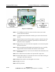
STEP 6 Slide PA module toward rear of chassis until RF output connector clears
the rear of the chassis.
STEP 7 Connect the W9 ribbon cable to the J6 connector on the PA interface
board.
STEP 8 Connect the W10 ribbon cable to J9 on the PA interface board.
STEP 9 Use a WAGO tool to connect power supply wires 54 & 55 to TB1 on the
interface board.
STEP 10 Connect the two RF connectors J3 & J4 to the coupler ports.
STEP 11 Connect the RF input cable J1 from PA module input port.
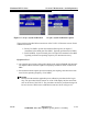
STEP 12 Install the nut (Figure 5-3) that fastens the PA module bracket to the
bottom of the chassis. Leave it loose.
STEP 13 Rotate the bracket on the PA module heat sink to align the bracket with
the screw hole on the right side of the transmitter chassis.
STEP 14 Install the PA module screw on the right side of the chassis. Thread this
screw into the L bracket attached to the PA module heat sink. Leave it
loose.
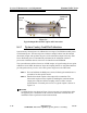
STEP 15 Install the two screws on the rear panel on either side of the output
connector. Be sure the PA module output connector is fully seated in the
rear chassis opening. Tighten the screws.
STEP 16 Tighten the L bracket screws, and the nut and screw holding the PA
module bracket in place.
STEP 17 Check the tightness of all connectors and hardware.
STEP 18 Replace cover and tighten screws.
STEP 19 Reapply AC power.
STEP 20 End of procedure.