
Specifications


5-4 888-2857-001 5/9/13
WARNING: Disconnect primary power prior to servicing.
Section 5 Maintenance and Alignments
Platinum VAX-C Series
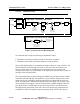
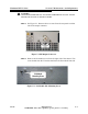
Figure 5-3 Amplifier Compartment
STEP 5 Loosen the screw that holds the L bracket to the PA module heat sink and
then rotate the L bracket 90
o
to allow maximum clearance during
module removal.
STEP 6 Remove the nut (Figure 5-3) that fastens the PA module bracket to the
bottom of the chassis.
!
CAUTION:
DO NOT DAMAGE COMPONENTS ON PA INTERFACE BOARD WHEN INSTALLING
THE PA MODULE FROM THE CHASSIS.
STEP 7
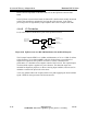
Remove the RF input cable J1 from PA module front.
STEP 8 Remove the two RF connectors J3 & J4 that attach to the coupler ports.
STEP 9 Use a WAGO tool to disconnect power supply wires 54 & 55 from TB1
on the interface board.
STEP 10 Remove the W10 ribbon cable from the J9 connector on the PA interface
board.
Nut
J3