
Specifications


5/9/13 888-2857-001 4-21
WARNING: Disconnect primary power prior to servicing.
Section 4 Theory of Operation
Platinum VAX-C Series
4.5 VAX-C Transmitter PAs
4.5.0.1 Fault Protection
Certain fault conditions warrant immediate, hardware-invoked shut-down of the power
supply and RF Drive to provide rapid system protection. Hardware comparators are
used in conjunction with the CPLD to provide fast shutdown and notification to the
signal processor in the event of the following fault conditions:
• Over current of any of the PA FETS
• Over voltage of the +50V power supply
• VSWR Protection in severe conditions too fast for and above the foldback threshold.
This level is automatically scaled to the system power level and operating frequency
(accounting for coupler response)
• Over temperature of either PA FET.
Trip levels appropriate to the system power level are automatically created. This is
important in the case of the VSWR fault, where there is a frequency dependent coupler
response. The system automatically determines the appropriate levels without
“tweaking” or user interaction.
When any fault occurs, the CPLD latches a Fault, which turns off the 50V power supply
and also pulls down the ALC attenuator control voltage on the UDC. This remove both
drive and voltage to the PA as quickly as possible to minimize the risk of damage in a
fault event.
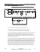
4.5.0.2 RF Power Detection and Calibration
The power detection circuitry was designed to facilitate ease of initial calibration and
eliminate the need for re-calibration on a change of frequency. It introduces the
following features:
• A microstrip coupling structure is used to provide optimum unit-to-unit repeatability
for forward and reflected power monitoring. The coupler includes 13dB attenuators
which are built into both the forward and reflected output ports. These attenuators
present a good return loss to the structure so that both ports may be used simultane-
ously while maintaining high directivity.
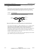
The forward and reflected samples feed a switch matrix and forward and reflected
detectors on the PA Interface. The signal processor can calculate required correction