
Specifications


4-20 888-2857-004 5/9/13
WARNING: Disconnect primary power prior to servicing.
Section 4 Theory of Operation
Platinum VAX-C Series
Down converter top board via J8 and is sent to J6 on the Up/Down converter base
board.
In the Up/Down converter base board, the filtered IF is buffered and variably attenuated
to allow the controller to optimize the level into the A/D converter in the signal
processing board. A high linearity output amplifier drives the IF output to the ADC.
4.4.8.5 LO Distribution
LO (Local Oscillator) distribution is part of the up/downconverter.
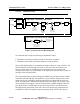
Figure 4-10 Up/Downconverter Bd, LO Distribution Circuit Block Diagram
The LO input from the PFRU is 0+/-2dBm, with harmonics of -10 to -15 dBc. It utilizes
a high frequency VCO (800-1600MHz) which is divided down to provide the LO
frequencies required for the Up/Down converter. For more consistent mixer
performance, it is desirable to have tighter control of the LO level. The coupled output
of a directional coupler is applied to a power detector. This detected output was
included for diagnostic purposes, to detect a missing input condition, and was used to
maintain a constant LO input level to the mixer.
A two-way splitter follows the coupler, with the two paths supplying the local oscillator
signal +7dBm for the upconverter and downconverter.
Detector
LO Level
Sample TO
800 MHz
Low Pass
2-Way
Splitter
LO Output
To Upconverter
LO Output
To Downconverter
System Controller
Coupler
Filter
J6, LO Input
PLL On The
PFRU Board