
Specifications


5/9/13 888-2857-001 4-19
WARNING: Disconnect primary power prior to servicing.
Section 4 Theory of Operation
Platinum VAX-C Series
4.4.8.4 Downconverter
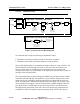
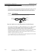
Figure 4-9 Downconverter Block Diagram
The downconverter accepts the following on-channel RF inputs:
• Transmitter system PA (pre-filter) sample for non-linear estimation.
• Transmitter system HPF (post-filter) sample for linear estimation.
The two RF sample inputs are each applied to a high-isolation two-way switch IC. The
selected sample is routed through its respective two-way switch to the final 2-way
selector switch, while the undesired input is switched into a resistive load. This
arrangement provides very good isolation of the signals and a good absorptive match to
the input in the de-selected state.
The selected RF sample is passed through a 900 MHz low pass filter and then variably
attenuated, buffered, and split. One path feeds a power detector which provides a DC
sample used by the controller to adjust the attenuator for optimum RF level into the
mixer. The other path is amplified and applied to the mixer input. The IF output of the
mixer is applied to a bridged-T network and buffered by a MMIC amplifier, then low-
pass filtered with a 225 MHz Mini circuits chip low-pass filter. This filter removes
unwanted mixing components from VHF conversions while being transparent to the
140MHz IF in terms of amplitude response and group delay. This IF leaves the up/
Switch
SPDT Non-
Reflective
Switch
SPDT Non-
Reflective
Switch
Variable
Attenuator
Controller
via a DAC
RMS
2-Way
Splitter
Detector
Input Power
Sample to
DAC
225 MHz
LPF
J14, LO Input
From PLL
Via LO Filter
140 MHz
BP Filter
J4, PA RF
Sample
J5, HPF RF
Sample
Variable
Attenuator
Controller, via a DAC,
Sets Optimum
ADC Input Level
J4, IF Output
To Signal Processor
Mixer Level
Sets Optimum
900 MHz
LPF
Board ADC
J8
J6
Up Down Converter Top Board
Up Down Converter Base Board