
Specifications


4-18 888-2857-004 5/9/13
WARNING: Disconnect primary power prior to servicing.
Section 4 Theory of Operation
Platinum VAX-C Series
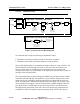
The signal is next sent to a two stage VHF tunable bandpass filter, which removes the
undesired mixing products. In each filter stage, the filtered RF is buffered by a MMIC
amplifier.
After the filtering process the RF signal is applied to a mute circuit, which consists of a
SPDT low-loss, high isolation (60dB @ 1.5GHz) microwave relay. When muted, the
normal RF path is opened and the RF switched into a 50 load.
The RF is then passed through a low pass filter and then gain adjusted by a variable
attenuator and sent to an amplifier. The amplifier is followed by a low-loss directional
coupler with the main coupler path leaving the up converter via J1 and sent to the power
amplifier assembly.
The coupled RF sample is applied to an AD8362 demodulating detector IC. The
detector output is heavily low-pass filtered to provide average power measurement.
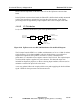
4.4.8.3 Downconverter Major Specifications
The downconverter includes two selectable RF RTAC (real time adaptive correction)
input samples, which are:
• The PA output RF sample, taken before the high power mask filter
• The high power mask filter RF sample, taken after the high power mask filter.
Downconverter input specifications:
• Frequency range is 168 to 242 MHz
• Input power range is -20 to +5 dBm, with the optimum input level -5 dBm