
Specifications


5/9/13 888-2857-001 4-17
WARNING: Disconnect primary power prior to servicing.
Section 4 Theory of Operation
Platinum VAX-C Series
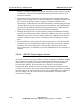
4.4.8.2 Functional Description of Upconverter
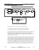
Figure 4-8 Upconverter Block Diagram
The upconverter base board accepts a 140MHz IF at a 0 dBm average level from the
Signal Processing board via J7. The 140 MHz IF is filtered primarily by the low-pass
portion of a bandpass filter which suppresses the unwanted DAC signals at 258MHz
and above. The filtered IF is applied to a variable attenuator which is used to set the
RMS level to the optimum level for the mixer in order to minimize spurious mixing
products. This attenuator is set to a specific fixed value by the system controller
depending on the modulation format. A directional coupler applies a sample of the IF to
a detector IC, which provides a voltage output proportional to the RMS level of the IF.
This voltage is A/D converted and utilized by the controller for diagnostic purposes,
primarily to detect a low/missing input condition. The signal leaves the base board via
J5 and is sent to the UDC top board.
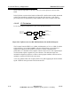
The IF signal enters the UDC top board via J7. The IF is applied to the mixer through a
fixed pad and a bridged T network. This provides a very good match, from DC to very
high frequencies, to the IF port of the mixer which helps to minimize 3rd order mixing
products, i.e. (2*IF)-LO. The mixer output is buffered by a MMIC (Monolithic
Microwave Integrated Circuit) amplifier.
168-242 MHz
VHF Tunable
LO Input
BP Filter
140 MHz
BP Filter
J7, 140 MHz
IF Input
at 0 dBm
ALC
Attenuator
Detector
50 Ohm
Load
J1, RF Output
to PA Assembly
6 dB Max Output
Mute
From Controller
Via a DAC
From PLL
Via LO
Distribution
Coupler
168-242 MHz
VHF Tunable
BP Filter
VCoupling
VTune
RF_Level_Out
Low
Pass
Filter
Up Down Converter Top Board
ALC
Attenuator
From Controller
Via a DAC
Detector
IF_Level_Out
Coupler
J7J5
Up Down Converter Base Board
From Signal
Processor
Board DAC