
Specifications


4-16 888-2857-004 5/9/13
WARNING: Disconnect primary power prior to servicing.
Section 4 Theory of Operation
Platinum VAX-C Series
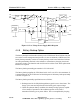
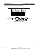
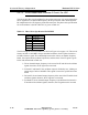
Figure 4-7 PFRU Board 10 MHz Reference Oscillator Circuit
4.4.7.4 PFRU Board GPS Circuit
The PFRU board includes a GPS receiver. The antenna input for the receiver is
connector J8 on the PFRU board. A 50 ohm coax connects this connector to the GPS
antenna input SMA connector on the modulator rear panel.
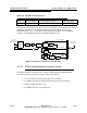
4.4.8 Up/Downconverter Board
This assembly consists of two piggy backed boards, the UDC Base and the UDC top
board. The assembly has three major circuits, which are as follows:
• The Upconverter
• The Downconverter
• The Local Oscillator Distribution
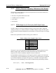
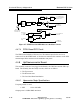
4.4.8.1 Upconverter Major Specifications
Frequency bands covered:
• BIII 168 to 242 MHz
Output power is 6 dBm RMS maximum
FPGA
and
Phase
Detector
Low Pass
Filter
VCO
Coupler
J4-16, 1 PPS
Reference Input
From Ref. Osc.
Low Pass
Filter
J3, 10 MHz Output
To Optional Repeater
Low Pass
Filter
Receiver Card
10 MHz To
RF UDC PLL
10 or 54 MHz To
DAC PLL
Q
D
Q
Resistive
DIvider
DAC Select
1 = 10 MHz
0 = 54 MHz
J6, 54 MHz
Input
54 MHz To
Level Detector