
Specifications


4-14 888-2857-004 5/9/13
WARNING: Disconnect primary power prior to servicing.
Section 4 Theory of Operation
Platinum VAX-C Series
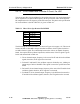
4.4.7.2 PFRU Board Local Oscillator-2 Circuit, For UDC
This circuit provides a local oscillator for the up/downconverter. It is used to heterodyne
the IF signal to the on channel RF frequency in the upconverter and to heterodyne the
RF sample back to the IF frequency in the downconverter. The phase noise specification
for local oscillator 2 (the RF UDC PLL) is given in Table 4-3.
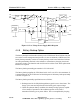
The block diagram of local oscillator 2 is shown in Figure 4-6 on page 4-15. This circuit
features an 800 to 1600 MHz voltage controlled oscillator, which is phase locked to a
10 MHz reference signal. The relationship between the various on channel frequency
bands, the required local oscillator frequencies, and the status of the IF signal is given
below and summarized in Table 4-4.
• The on channel output frequency is the sum of the IF and the local oscillator
signals, therefore, the IF signal is not inverted.
• For band V and band IV, the oscillator output is divided by two, yielding an
output range of 400 to 800 MHz. This signal is sent to the up/downconverter
board.
• For band V, the on channel output frequency is the sum of the IF and the local
oscillator signals, therefore, the IF signal is not inverted.
• For Band IV, the on channel output frequency is the difference between the
IF and the local oscillator signals, therefore, the IF signal must be inverted.
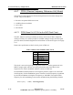
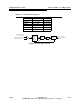
Table 4-3 Phase Noise Specification For RF PLL
Hertz B IV, B V
10 -57 dBc/Hz
100 -87 dBc/Hz
1k -92 dBc/Hz
10k -97 dBc/Hz
100k -114 dBc/Hz
1M -132 dBc/Hz