
Specifications


4-8 888-2857-004 5/9/13
WARNING: Disconnect primary power prior to servicing.
Section 4 Theory of Operation
Platinum VAX-C Series
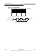
The signal is next applied to a mixer, along with the local oscillator signal from the 2nd
local oscillator phase lock loop circuit in the precise frequency reference board.
The resultant 140 MHz IF signal is then filtered to remove mixing products and sent to
an attenuator controlled from the signal processor board. Here its level is set to
optimum for its next destination, the ADC (Analog to Digital Converter) in the signal
processor board.
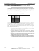
In the ADC, the IF signal is digitized and sent to the digital precorrector (RTAC) circuit.
RTAC performs two functions, which are:
• Non-linear precorrection to cancel the phase and linearity distortions created in the
drivers and PA
• Linear precorrection to cancel the amplitude response and group delay) distortions
created in the high power filter.
4.4.4 Low Voltage Power Supply Board
The low voltage power supply for the modulator is mounted to the left inside wall of the
transmitter chassis. The following items are mounted on the power supply assembly:
• The AC Input connector.
• A +12V switching power supply, mounted towards the rear of the power
supply assembly.
• Provision for an optional battery backup board, mounted at the front of the
power supply board.
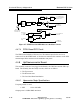
• The LVPS distribution board receives +12 Vdc from the switching supply. It
uses it to generate the +24Vdc, +5Vdc, and -12Vdc outputs from dc to dc
converters.
• The +24V, +12V, +12Vosc, +5V, and -12V are dc outputs supplied via a
ribbon cable to the signal processor board. Power to the other boards is
distributed via the signal processing board to the other subsystems.
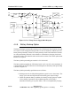
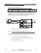
The block diagram of the low voltage power supply is shown in Figure 4-3.
The part number for the power supply board, including the switching supply, is 971-
0051-011G.